はじめに
ArduinoでESP32のI2Sを使用するにはいくつかの方法があるようですが、公式のESP-IDF Porgramming Guideでnew driverとされているi2s_std.h/i2s_pdm.h/i2s_tdm.hのうちi2s_pdm.hをインクルードして秋月電子さんで販売されているSPH0641LU4H使用 超広帯域マイクモジュールキットをESP32-S3に接続して使用してみました。
環境
- Arduino IDE 2.3.5
- ボードマネージャー esp32 by Espressif 3.2.0
- デバイス ESP32-S3 Dev Module 互換ボード
- マイク SPH0641LU4H使用 超広帯域マイクモジュールキット
ESP-IDFのI2S APIのファイル構成について
公式のガイドには次のように書かれています。

Public headers that need to be included in the I2S application are as follows:
・i2s.h: The header file that provides legacy I2S APIs (for apps using legacy driver).
・i2s_std.h: The header file that provides standard communication mode specific APIs (for apps using new driver with standard mode).
・i2s_pdm.h: The header file that provides PDM communication mode specific APIs (for apps using new driver with PDM mode).
・i2s_tdm.h: The header file that provides TDM communication mode specific APIs (for apps using new driver with TDM mode).
ArduinoでESP32シリーズのI2Sを使用する場合<driver/i2s.h>をインクルードしている例はネットでもよく見かけるのですがi2s_std.hやi2s_pdm.h, i2s_tdm.hを使用している例は今のところあまり見かけません。
ESP32-S3は比較的新しいシリーズなのでAPIも新しい<driver/i2s_pdm.h>を使ったほうが良いのではないかと根拠の薄い思い込みで動作確認用のスケッチを書いてみることにしました。
ちなみに広く使われているArduinoライブラリESP32-audioI2SではESP-IDFのバージョンによってインクルードファイルを切り替えているようです。
#if ESP_IDF_VERSION_MAJOR == 5
#include <driver/i2s_std.h>
#else
#include <driver/i2s.h>
#endif
PDM(パルス密度変調)マイクについて
Wikipediaにわかりやすく説明されています。
PDMマイクとESP-S3の接続はクロックとデータの2本だけとなります。またESP32-S3にはPDMとPCMの相互変換回路が内蔵されており、PDM-to-PCM RX modeの変換を行って入力されるPDMマイク出力をPCMデータとして取り込むことが可能です。
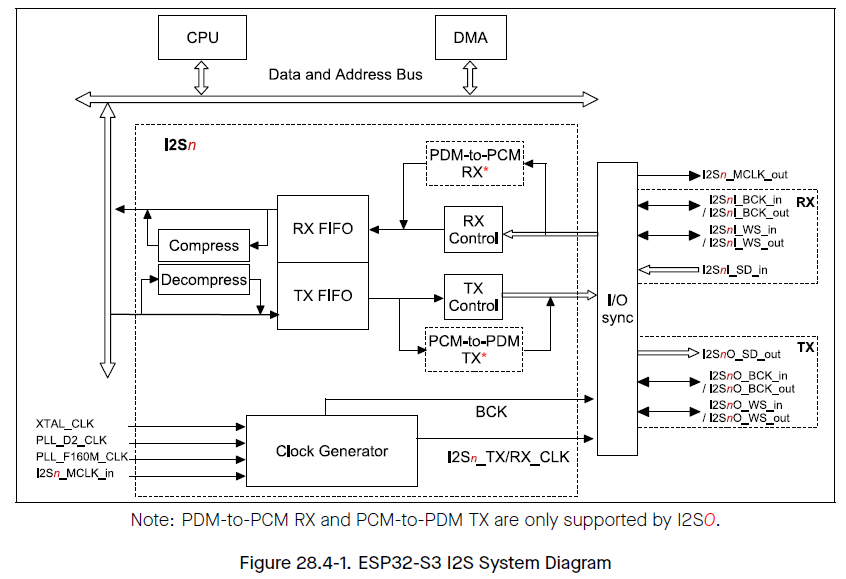
(ESP32-S3 Technical Reference Manualより)
PDMモードでは上図のI2SnI_WS_outがPDMクロックに、I2SnI_SD_INがPDMデータに相当するので、これらをI2SのWSとDINとしてピン設定します。
スケッチ
#include <driver/i2s_pdm.h>               // (1)

// (2)
#define I2S_SAMPLE_RATE     48000
#define I2S_BUFFER_SIZE     1024
#define I2S_PIN_PDMCLK 15
#define I2S_PIN_PDMDIN 16

int16_t i2s_sambles[I2S_BUFFER_SIZE];
i2s_chan_handle_t rx_handle = NULL;      // (3)

// SPH0641LU4H PDM microphone setting
void pdmMicInit() {
  // I2S controller channel configuration
  i2s_chan_config_t chan_cfg = {        // (4)
    .id = I2S_NUM_AUTO,             // I2S port id
    .role = I2S_ROLE_MASTER,        // or I2S_ROLE_SLAVE
    .dma_desc_num = 6,              // I2S DMA buffer number, it is also the number of DMA descriptor
    .dma_frame_num = 256,           // I2S frame number in one DMA buffer.
                                    // One frame means one-time sample data in all slots,
                                    // it should be the multiple of `3` when the data bit width is 24
    .auto_clear_after_cb = false,   // Alias of `auto_clear_after_cb
    .auto_clear_before_cb = false,  // Set to auto clear DMA TX buffer after `on_sent` callback
    .allow_pd = false,              // power down control
    .intr_priority = 0,
  };
//  i2s_chan_config_t chan_cfg = I2S_CHANNEL_DEFAULT_CONFIG(I2S_NUM_AUTO, I2S_ROLE_MASTER);
  ESP_ERROR_CHECK(i2s_new_channel(&chan_cfg, NULL, &rx_handle));

  // Clock Configuraiton             // (5)
  i2s_pdm_rx_clk_config_t clk_cfg {
    .sample_rate_hz = I2S_SAMPLE_RATE,      // sample rate
    .clk_src = I2S_CLK_SRC_DEFAULT,         // PLL_D2_CLK (240HMz, when PLL=480MHz) or I2S_CLK_SRC_PLL_160M
    .mclk_multiple = I2S_MCLK_MULTIPLE_256, // master clock, or I2S_MCLK_MULTIPLE_384
    .dn_sample_mode = I2S_PDM_DSR_8S,       // down sample rate 64 or I2S_PDM_DSR_16S 128
    .bclk_div = 8,                          // fixed
  };

  // Slot Configuration            // (6)
  i2s_pdm_rx_slot_config_t slot_cfg = {
    .data_bit_width = I2S_DATA_BIT_WIDTH_16BIT,
    .slot_bit_width = I2S_SLOT_BIT_WIDTH_AUTO,
    .slot_mode = I2S_SLOT_MODE_MONO,    // or I2S_SLOT_MODE_STEREO
    .slot_mask = I2S_PDM_SLOT_LEFT,     // or I2S_PDM_SLOT_BOTH in stereo
  };

  i2s_pdm_rx_config_t pdm_rx_cfg = {    // (7)
    .clk_cfg = clk_cfg,
    .slot_cfg = slot_cfg,
    .gpio_cfg = {
      .clk = (gpio_num_t)I2S_PIN_PDMCLK,
      .din = (gpio_num_t)I2S_PIN_PDMDIN,
      .invert_flags = {
        .clk_inv = false,
      },
    },
  };
  ESP_ERROR_CHECK(i2s_channel_init_pdm_rx_mode(rx_handle, &pdm_rx_cfg));
  ESP_ERROR_CHECK(i2s_channel_enable(rx_handle));
}

void setup() {
  Serial.begin(115200);
  delay(1000);

  pdmMicInit();
}

/**
 * @brief I2S read data
 * @note  Only allowed to be called when the channel state is RUNNING
 *        but the RUNNING only stands for the software state, it doesn't mean there is no the signal transporting on line.
 *
 * @param[in]   handle      I2S channel handler
 * @param[in]   dest        The pointer of receiving data buffer
 * @param[in]   size        Max data buffer length
 * @param[out]  bytes_read      Byte number that actually be read, can be NULL if not needed
 * @param[in]   timeout_ms      Max block time
 * @return
 *      - ESP_OK    Read successfully
 *      - ESP_ERR_INVALID_ARG   NULL pointer or this handle is not RX handle
 *      - ESP_ERR_TIMEOUT       Reading timeout, no reading event received from ISR within ticks_to_wait
 *      - ESP_ERR_INVALID_STATE I2S is not ready to read
 */

void loop() {
  static unsigned long ut_now = 0, ut_past = 0;
  size_t bytes_read;

  // esp_err_t i2s_channel_read(    // (8)
  //    i2s_chan_handle_t handle,     // I2S channel handler
  //    void *dest,                   // The pointer of receiving data buffer
  //    size_t size,                  // Max data buffer length
  //    size_t *bytes_read,           // Byte number that actually be read, can be NULL if not needed
  //    uint32_t timeout_ms)          // Max block time
  // This is a blocking function, blocks until the whole destination buffer is loaded.
  i2s_channel_read(rx_handle, (void *)i2s_sambles, sizeof(i2s_sambles), &bytes_read, portMAX_DELAY);

  // measure time
  ut_now = micros();
  Serial.printf("Time us: %6d\n", ut_now - ut_past);
  ut_past = ut_now;

  // Display numer of byte
  Serial.printf("read %6d bytes\n", bytes_read);
  // Display only the first data
  Serial.printf("%6d\n", i2s_sambles[0]);

}
コードの要点について説明します。
- <driver/i2s_pdm.h>をインクルード
- サンプルレート(Hz)、バッファサイズを定義
PDMのサンプルレートfSMPはクロックソースfSRCと以下の関係になります。
fSMP×64×8×(N + b/a) = fSRC
ここで64はPDM to PCMのダウンサンプリングレートです。8はビットクロックレートで固定値です。(N + a/b)は内蔵されるfractional分周器での分周比になります。上記例のfSMP = 48KHzの場合 N = 9, a = 64, b = 49となり、分周後のPDMクロックにはjitterが載ることになります。CD/DVDのサンプリングレートに合わせる必要が無い場合はfractional部が0になるように設定するほうが精度の良いキャプチャができると思われます。 - i2sチャンネルへのハンドルを定義しておきます。ここはLegacyドライバと異なる部分です。
- チャンネルのコンフィギュレーションをおこなっています。dma_frame_numとI2S_BUFFER_SIZEを公約にすることで後のi2s_channel_read()でのバッファデータ取得間隔が安定するようです。
- クロックのコンフィグレーションを行っています。PDMではmaster clockは使用しません。
- スロットのコンフィグレーションを行っています。PDMではdata_bit_wifthは16固定です。
- PDM RXチャンネルにクロック、スロット、ピン指定のコンフィグレーションを適用し、チャンネルを有効化しています。
- i2s_channel_read()ファンクションを用いてI2S_BUFFER_SIZE分のPCMデータを取得しています。この関数は指定サイズのデータを取得するまでブロックします。タイムアウト時間(timeout_ms)を指定することも可能です。
実行結果
Time us:  21334
read   2048 bytes
    19
Time us:  21333
read   2048 bytes
    40
Time us:  21333
read   2048 bytes
   -65
Time us:  21334
read   2048 bytes
   126
Time us:  21333
read   2048 bytes
  -149
Time us:  21333
read   2048 bytes
   197
Time us:  21334
read   2048 bytes
  -211
Time us:  21333
read   2048 bytes
   243
Time us:  21333
read   2048 bytes
  -249
Time us:  21334
read   2048 bytes
   261
1バッファ分の取得時間は21333us~21334usでこれは1024/48000 = 213.3333...usとほぼ一致します。
下図はソースを少し書き換えて2KHzのサイン波音源のキャプチャデータをプロットしたものです。DCオフセットがかなり載ってしまっていますが波形と周期は正しく取得できています。

最後に
new driver with PDM modeを使用したアプリケーションの為の備忘録としてこの記事を書きました。
どなたかのお役に立てれば幸いです。