ESP32マイコンを搭載した液晶ディスプレイモジュールの中でも、「Cheap Yellow Display (CYD)」シリーズの ESP32-2432S028R を使ったUIデザインを行う。
インターネット上には EEZ studio というオープンソースのGUIデザインツールを使ってディスプレイ付きesp32を動かしている日本語の記事がほとんど見当たらなかったので、今回まとめてみました。
EZZ Studioについて
組み込みシステムやマイコン向けのGUIデザインツールは複数ありますが、一番有名な SquareLine Studio は商用利用の場合に費用がかかります(個人事業主でも月30,000円程度)。
一方、 EEZ Studio はオープンソースで無料で利用できるGUIツールです。
このツールは LVGL というグラフィックライブラリをベースにしています。
LVGL(Light and Versatile Graphics Library)
組み込みシステムやマイコン向けの軽量なオープンソースのグラフィックライブラリ。
ディスプレイライブラリについて
グラフィックライブラリ(LVGL)とは別に、ディスプレイ表示用のライブラリも必要です。ESP32向けには主に以下の2つがあります。
-
LovyanGFX
日本語対応しており、日本語の情報も豊富です。オート機能によりディスプレイの自動検出が可能で、初期設定が比較的簡単です。 -
TFT_eSPI
初期設定はやや難しいですが、LVGLとの統合がすでに確立されています。
なお、ライブラリやボードのバージョンによっては競合が発生する場合があり、ネット上のコードを流用してもバージョンが違うとエラーが出る可能性があります。
以下の環境で行うことで、安定した実装が可能です。
環境(バージョン)
| 環境 | 名称 | バージョン |
|---|---|---|
| 開発環境 | Arduino IDE | v2.3.4 |
| ボードマネージャー | esp32 by Espressif | v3.2.0 |
| グラフィックライブラリ | LVGL | v9.2.2 |
| ディスプレイライブラリ | tft_eSPI | v2.5.43 |
| タッチスクリーンライブラリ | XPT2046_Touchscreen | v1.4 |
| GUIデザインツール | EEZ Studio | v0.23.1 |
準備
Arduino
環境設定
-
マザーボード : EESP32_2432S028
-
ディスプレイ : 2.8″ 240×320 SPI ILI9341V LCD
-
タッチパネル:Touch XPT2046
-
環境開発 : Arduino IDE 1.8.19
-
推奨ボードマネージャー : esp32 by Espressif System 2.0.14
-
ボード : “ESP32 Dev Module”
-
ポート : “dev/cu.wchusbserial14240”
- CPU Frequency : “240MHz (WiFi/BT)”
- Core Degug Level : “None”
- Erase All Flash Before Sketch Upload : “Disabled”
- Events Run On : “Core 1”
- Flash Frequency : “80MHz”
- Flash Mode : “QIO” or “DIO”
- Flash Size : “4MB (32Mb)”
- JTAG Adaptor : “Disabled”
- Arduino Runs On : “Core 1”
- Partition Scheme : “Default 4MB with spiffs (1.2MB APP/1.5MB SPIFFS)”
- PSRAM : “Disabled”
- Upload Speed : “115200”
tft_espiの設定
設定方法は2通りあります:
プロジェクト単位で設定する場合(他のデバイスでも使いたい場合)
• User_Setup.h をプロジェクトファイルのルートに配置
ライブラリ全体に設定したい場合
• TFT_eSPI ライブラリフォルダ内の User_Setup.h をArduinoライブラリ直下に移動
/Users/Your_name/Documents/Arduino
User_Setup.hのサンプル
/*
  Rui Santos & Sara Santos - Random Nerd Tutorials

  Install the "TFT_eSPI" lbirary by Bodmer to interface with the TFT Display - https://github.com/Bodmer/TFT_eSPI
  *** IMPORTANT: User_Setup.h available on the internet will probably NOT work with the examples available at Random Nerd Tutorials ***
  *** YOU MUST USE THIS User_Setup.h FILE, CHECK FOR THE LATEST VERSION IN THE LINK BELOW IN ORDER TO USE THE EXAMPLES FROM RANDOM NERD TUTORIALS ***
  https://RandomNerdTutorials.com/cyd/
  https://RandomNerdTutorials.com/esp32-tft/
  FULL INSTRUCTIONS AVAILABLE ON HOW CONFIGURE THE LIBRARY: https://RandomNerdTutorials.com/cyd/ or https://RandomNerdTutorials.com/esp32-tft/
*/

//                            USER DEFINED SETTINGS
//   Set driver type, fonts to be loaded, pins used and SPI control method etc
//
//   See the User_Setup_Select.h file if you wish to be able to define multiple
//   setups and then easily select which setup file is used by the compiler.
//
//   If this file is edited correctly then all the library example sketches should
//   run without the need to make any more changes for a particular hardware setup!
//   Note that some sketches are designed for a particular TFT pixel width/height

// User defined information reported by "Read_User_Setup" test & diagnostics example
#define USER_SETUP_INFO "User_Setup"

// Define to disable all #warnings in library (can be put in User_Setup_Select.h)
//#define DISABLE_ALL_LIBRARY_WARNINGS

// ##################################################################################
//
// Section 1. Call up the right driver file and any options for it
//
// ##################################################################################

// Define STM32 to invoke optimised processor support (only for STM32)
//#define STM32

// Defining the STM32 board allows the library to optimise the performance
// for UNO compatible "MCUfriend" style shields
//#define NUCLEO_64_TFT
//#define NUCLEO_144_TFT

// STM32 8 bit parallel only:
// If STN32 Port A or B pins 0-7 are used for 8 bit parallel data bus bits 0-7
// then this will improve rendering performance by a factor of ~8x
//#define STM_PORTA_DATA_BUS
//#define STM_PORTB_DATA_BUS

// Tell the library to use parallel mode (otherwise SPI is assumed)
//#define TFT_PARALLEL_8_BIT
//#defined TFT_PARALLEL_16_BIT // **** 16 bit parallel ONLY for RP2040 processor ****

// Display type -  only define if RPi display
//#define RPI_DISPLAY_TYPE // 20MHz maximum SPI

// Only define one driver, the other ones must be commented out
//#define ILI9341_DRIVER       // Generic driver for common displays
#define ILI9341_2_DRIVER     // Alternative ILI9341 driver, see https://github.com/Bodmer/TFT_eSPI/issues/1172
//#define ST7735_DRIVER      // Define additional parameters below for this display
//#define ILI9163_DRIVER     // Define additional parameters below for this display
//#define S6D02A1_DRIVER
//#define RPI_ILI9486_DRIVER // 20MHz maximum SPI
//#define HX8357D_DRIVER
//#define ILI9481_DRIVER
//#define ILI9486_DRIVER
//#define ILI9488_DRIVER     // WARNING: Do not connect ILI9488 display SDO to MISO if other devices share the SPI bus (TFT SDO does NOT tristate when CS is high)
//#define ST7789_DRIVER      // Full configuration option, define additional parameters below for this display
//#define ST7789_2_DRIVER    // Minimal configuration option, define additional parameters below for this display
//#define R61581_DRIVER
//#define RM68140_DRIVER
//#define ST7796_DRIVER
//#define SSD1351_DRIVER
//#define SSD1963_480_DRIVER
//#define SSD1963_800_DRIVER
//#define SSD1963_800ALT_DRIVER
//#define ILI9225_DRIVER
//#define GC9A01_DRIVER

// Some displays support SPI reads via the MISO pin, other displays have a single
// bi-directional SDA pin and the library will try to read this via the MOSI line.
// To use the SDA line for reading data from the TFT uncomment the following line:

// #define TFT_SDA_READ      // This option is for ESP32 ONLY, tested with ST7789 and GC9A01 display only

// For ST7735, ST7789 and ILI9341 ONLY, define the colour order IF the blue and red are swapped on your display
// Try ONE option at a time to find the correct colour order for your display

//  #define TFT_RGB_ORDER TFT_RGB  // Colour order Red-Green-Blue
//  #define TFT_RGB_ORDER TFT_BGR  // Colour order Blue-Green-Red

// For M5Stack ESP32 module with integrated ILI9341 display ONLY, remove // in line below

// #define M5STACK

// For ST7789, ST7735, ILI9163 and GC9A01 ONLY, define the pixel width and height in portrait orientation
// #define TFT_WIDTH  80
// #define TFT_WIDTH  128
// #define TFT_WIDTH  172 // ST7789 172 x 320
#define TFT_WIDTH  240 // ST7789 240 x 240 and 240 x 320
// #define TFT_HEIGHT 160
// #define TFT_HEIGHT 128
// #define TFT_HEIGHT 240 // ST7789 240 x 240
#define TFT_HEIGHT 320 // ST7789 240 x 320
// #define TFT_HEIGHT 240 // GC9A01 240 x 240

// For ST7735 ONLY, define the type of display, originally this was based on the
// colour of the tab on the screen protector film but this is not always true, so try
// out the different options below if the screen does not display graphics correctly,
// e.g. colours wrong, mirror images, or stray pixels at the edges.
// Comment out ALL BUT ONE of these options for a ST7735 display driver, save this
// this User_Setup file, then rebuild and upload the sketch to the board again:

// #define ST7735_INITB
// #define ST7735_GREENTAB
// #define ST7735_GREENTAB2
// #define ST7735_GREENTAB3
// #define ST7735_GREENTAB128    // For 128 x 128 display
// #define ST7735_GREENTAB160x80 // For 160 x 80 display (BGR, inverted, 26 offset)
// #define ST7735_ROBOTLCD       // For some RobotLCD arduino shields (128x160, BGR, https://docs.arduino.cc/retired/getting-started-guides/TFT)
// #define ST7735_REDTAB
// #define ST7735_BLACKTAB
// #define ST7735_REDTAB160x80   // For 160 x 80 display with 24 pixel offset

// If colours are inverted (white shows as black) then uncomment one of the next
// 2 lines try both options, one of the options should correct the inversion.

#define TFT_INVERSION_ON
// #define TFT_INVERSION_OFF


// ##################################################################################
//
// Section 2. Define the pins that are used to interface with the display here
//
// ##################################################################################

// If a backlight control signal is available then define the TFT_BL pin in Section 2
// below. The backlight will be turned ON when tft.begin() is called, but the library
// needs to know if the LEDs are ON with the pin HIGH or LOW. If the LEDs are to be
// driven with a PWM signal or turned OFF/ON then this must be handled by the user
// sketch. e.g. with digitalWrite(TFT_BL, LOW);

#define TFT_BL   21            // LED back-light control pin
#define TFT_BACKLIGHT_ON HIGH  // Level to turn ON back-light (HIGH or LOW)


// We must use hardware SPI, a minimum of 3 GPIO pins is needed.
// Typical setup for ESP8266 NodeMCU ESP-12 is :
//
// Display SDO/MISO  to NodeMCU pin D6 (or leave disconnected if not reading TFT)
// Display LED       to NodeMCU pin VIN (or 5V, see below)
// Display SCK       to NodeMCU pin D5
// Display SDI/MOSI  to NodeMCU pin D7
// Display DC (RS/AO)to NodeMCU pin D3
// Display RESET     to NodeMCU pin D4 (or RST, see below)
// Display CS        to NodeMCU pin D8 (or GND, see below)
// Display GND       to NodeMCU pin GND (0V)
// Display VCC       to NodeMCU 5V or 3.3V
//
// The TFT RESET pin can be connected to the NodeMCU RST pin or 3.3V to free up a control pin
//
// The DC (Data Command) pin may be labelled AO or RS (Register Select)
//
// With some displays such as the ILI9341 the TFT CS pin can be connected to GND if no more
// SPI devices (e.g. an SD Card) are connected, in this case comment out the #define TFT_CS
// line below so it is NOT defined. Other displays such at the ST7735 require the TFT CS pin
// to be toggled during setup, so in these cases the TFT_CS line must be defined and connected.
//
// The NodeMCU D0 pin can be used for RST
//
//
// Note: only some versions of the NodeMCU provide the USB 5V on the VIN pin
// If 5V is not available at a pin you can use 3.3V but backlight brightness
// will be lower.


// ###### EDIT THE PIN NUMBERS IN THE LINES FOLLOWING TO SUIT YOUR ESP8266 SETUP ######

// For NodeMCU - use pin numbers in the form PIN_Dx where Dx is the NodeMCU pin designation
//#define TFT_CS   PIN_D8  // Chip select control pin D8
//#define TFT_DC   PIN_D3  // Data Command control pin
//#define TFT_RST  PIN_D4  // Reset pin (could connect to NodeMCU RST, see next line)
//#define TFT_RST  -1    // Set TFT_RST to -1 if the display RESET is connected to NodeMCU RST or 3.3V

//#define TFT_BL PIN_D1  // LED back-light (only for ST7789 with backlight control pin)

//#define TOUCH_CS PIN_D2     // Chip select pin (T_CS) of touch screen

//#define TFT_WR PIN_D2       // Write strobe for modified Raspberry Pi TFT only


// ######  FOR ESP8266 OVERLAP MODE EDIT THE PIN NUMBERS IN THE FOLLOWING LINES  ######

// Overlap mode shares the ESP8266 FLASH SPI bus with the TFT so has a performance impact
// but saves pins for other functions. It is best not to connect MISO as some displays
// do not tristate that line when chip select is high!
// Note: Only one SPI device can share the FLASH SPI lines, so a SPI touch controller
// cannot be connected as well to the same SPI signals.
// On NodeMCU 1.0 SD0=MISO, SD1=MOSI, CLK=SCLK to connect to TFT in overlap mode
// On NodeMCU V3  S0 =MISO, S1 =MOSI, S2 =SCLK
// In ESP8266 overlap mode the following must be defined

//#define TFT_SPI_OVERLAP

// In ESP8266 overlap mode the TFT chip select MUST connect to pin D3
//#define TFT_CS   PIN_D3
//#define TFT_DC   PIN_D5  // Data Command control pin
//#define TFT_RST  PIN_D4  // Reset pin (could connect to NodeMCU RST, see next line)
//#define TFT_RST  -1  // Set TFT_RST to -1 if the display RESET is connected to NodeMCU RST or 3.3V


// ###### EDIT THE PIN NUMBERS IN THE LINES FOLLOWING TO SUIT YOUR ESP32 SETUP   ######

// For ESP32 Dev board (only tested with ILI9341 display)
// The hardware SPI can be mapped to any pins

#define TFT_MISO 12
#define TFT_MOSI 13
#define TFT_SCLK 14
#define TFT_CS   15  // Chip select control pin
#define TFT_DC    2  // Data Command control pin
//#define TFT_RST   4  // Reset pin (could connect to RST pin)
#define TFT_RST  -1  // Set TFT_RST to -1 if display RESET is connected to ESP32 board RST

#define TOUCH_CS 33     // Chip select pin (T_CS) of touch screen

// For ESP32 Dev board (only tested with GC9A01 display)
// The hardware SPI can be mapped to any pins

//#define TFT_MOSI 15 // In some display driver board, it might be written as "SDA" and so on.
//#define TFT_SCLK 14
//#define TFT_CS   5  // Chip select control pin
//#define TFT_DC   27  // Data Command control pin
//#define TFT_RST  33  // Reset pin (could connect to Arduino RESET pin)
//#define TFT_BL   22  // LED back-light

//#define TOUCH_CS 21     // Chip select pin (T_CS) of touch screen

//#define TFT_WR 22    // Write strobe for modified Raspberry Pi TFT only

// For the M5Stack module use these #define lines
//#define TFT_MISO 19
//#define TFT_MOSI 23
//#define TFT_SCLK 18
//#define TFT_CS   14  // Chip select control pin
//#define TFT_DC   27  // Data Command control pin
//#define TFT_RST  33  // Reset pin (could connect to Arduino RESET pin)
//#define TFT_BL   32  // LED back-light (required for M5Stack)

// ######       EDIT THE PINs BELOW TO SUIT YOUR ESP32 PARALLEL TFT SETUP        ######

// The library supports 8 bit parallel TFTs with the ESP32, the pin
// selection below is compatible with ESP32 boards in UNO format.
// Wemos D32 boards need to be modified, see diagram in Tools folder.
// Only ILI9481 and ILI9341 based displays have been tested!

// Parallel bus is only supported for the STM32 and ESP32
// Example below is for ESP32 Parallel interface with UNO displays

// Tell the library to use 8 bit parallel mode (otherwise SPI is assumed)
//#define TFT_PARALLEL_8_BIT

// The ESP32 and TFT the pins used for testing are:
//#define TFT_CS   33  // Chip select control pin (library pulls permanently low
//#define TFT_DC   15  // Data Command control pin - must use a pin in the range 0-31
//#define TFT_RST  32  // Reset pin, toggles on startup

//#define TFT_WR    4  // Write strobe control pin - must use a pin in the range 0-31
//#define TFT_RD    2  // Read strobe control pin

//#define TFT_D0   12  // Must use pins in the range 0-31 for the data bus
//#define TFT_D1   13  // so a single register write sets/clears all bits.
//#define TFT_D2   26  // Pins can be randomly assigned, this does not affect
//#define TFT_D3   25  // TFT screen update performance.
//#define TFT_D4   17
//#define TFT_D5   16
//#define TFT_D6   27
//#define TFT_D7   14

// ######       EDIT THE PINs BELOW TO SUIT YOUR STM32 SPI TFT SETUP        ######

// The TFT can be connected to SPI port 1 or 2
//#define TFT_SPI_PORT 1 // SPI port 1 maximum clock rate is 55MHz
//#define TFT_MOSI PA7
//#define TFT_MISO PA6
//#define TFT_SCLK PA5

//#define TFT_SPI_PORT 2 // SPI port 2 maximum clock rate is 27MHz
//#define TFT_MOSI PB15
//#define TFT_MISO PB14
//#define TFT_SCLK PB13

// Can use Ardiuno pin references, arbitrary allocation, TFT_eSPI controls chip select
//#define TFT_CS   D5 // Chip select control pin to TFT CS
//#define TFT_DC   D6 // Data Command control pin to TFT DC (may be labelled RS = Register Select)
//#define TFT_RST  D7 // Reset pin to TFT RST (or RESET)
// OR alternatively, we can use STM32 port reference names PXnn
//#define TFT_CS   PE11 // Nucleo-F767ZI equivalent of D5
//#define TFT_DC   PE9  // Nucleo-F767ZI equivalent of D6
//#define TFT_RST  PF13 // Nucleo-F767ZI equivalent of D7

//#define TFT_RST  -1   // Set TFT_RST to -1 if the display RESET is connected to processor reset
                        // Use an Arduino pin for initial testing as connecting to processor reset
                        // may not work (pulse too short at power up?)

// ##################################################################################
//
// Section 3. Define the fonts that are to be used here
//
// ##################################################################################

// Comment out the #defines below with // to stop that font being loaded
// The ESP8366 and ESP32 have plenty of memory so commenting out fonts is not
// normally necessary. If all fonts are loaded the extra FLASH space required is
// about 17Kbytes. To save FLASH space only enable the fonts you need!

#define LOAD_GLCD   // Font 1. Original Adafruit 8 pixel font needs ~1820 bytes in FLASH
#define LOAD_FONT2  // Font 2. Small 16 pixel high font, needs ~3534 bytes in FLASH, 96 characters
#define LOAD_FONT4  // Font 4. Medium 26 pixel high font, needs ~5848 bytes in FLASH, 96 characters
#define LOAD_FONT6  // Font 6. Large 48 pixel font, needs ~2666 bytes in FLASH, only characters 1234567890:-.apm
#define LOAD_FONT7  // Font 7. 7 segment 48 pixel font, needs ~2438 bytes in FLASH, only characters 1234567890:-.
#define LOAD_FONT8  // Font 8. Large 75 pixel font needs ~3256 bytes in FLASH, only characters 1234567890:-.
//#define LOAD_FONT8N // Font 8. Alternative to Font 8 above, slightly narrower, so 3 digits fit a 160 pixel TFT
#define LOAD_GFXFF  // FreeFonts. Include access to the 48 Adafruit_GFX free fonts FF1 to FF48 and custom fonts

// Comment out the #define below to stop the SPIFFS filing system and smooth font code being loaded
// this will save ~20kbytes of FLASH
#define SMOOTH_FONT


// ##################################################################################
//
// Section 4. Other options
//
// ##################################################################################

// For RP2040 processor and SPI displays, uncomment the following line to use the PIO interface.
//#define RP2040_PIO_SPI // Leave commented out to use standard RP2040 SPI port interface

// For RP2040 processor and 8 or 16 bit parallel displays:
// The parallel interface write cycle period is derived from a division of the CPU clock
// speed so scales with the processor clock. This means that the divider ratio may need
// to be increased when overclocking. I may also need to be adjusted dependant on the
// display controller type (ILI94341, HX8357C etc). If RP2040_PIO_CLK_DIV is not defined
// the library will set default values which may not suit your display.
// The display controller data sheet will specify the minimum write cycle period. The
// controllers often work reliably for shorter periods, however if the period is too short
// the display may not initialise or graphics will become corrupted.
// PIO write cycle frequency = (CPU clock/(4 * RP2040_PIO_CLK_DIV))
//#define RP2040_PIO_CLK_DIV 1 // 32ns write cycle at 125MHz CPU clock
//#define RP2040_PIO_CLK_DIV 2 // 64ns write cycle at 125MHz CPU clock
//#define RP2040_PIO_CLK_DIV 3 // 96ns write cycle at 125MHz CPU clock

// For the RP2040 processor define the SPI port channel used (default 0 if undefined)
//#define TFT_SPI_PORT 1 // Set to 0 if SPI0 pins are used, or 1 if spi1 pins used

// For the STM32 processor define the SPI port channel used (default 1 if undefined)
//#define TFT_SPI_PORT 2 // Set to 1 for SPI port 1, or 2 for SPI port 2

// Define the SPI clock frequency, this affects the graphics rendering speed. Too
// fast and the TFT driver will not keep up and display corruption appears.
// With an ILI9341 display 40MHz works OK, 80MHz sometimes fails
// With a ST7735 display more than 27MHz may not work (spurious pixels and lines)
// With an ILI9163 display 27 MHz works OK.

// #define SPI_FREQUENCY   1000000
// #define SPI_FREQUENCY   5000000
// #define SPI_FREQUENCY  10000000
// #define SPI_FREQUENCY  20000000
//#define SPI_FREQUENCY  27000000
// #define SPI_FREQUENCY  40000000
#define SPI_FREQUENCY  55000000 // STM32 SPI1 only (SPI2 maximum is 27MHz)
// #define SPI_FREQUENCY  80000000

// Optional reduced SPI frequency for reading TFT
#define SPI_READ_FREQUENCY  20000000

// The XPT2046 requires a lower SPI clock rate of 2.5MHz so we define that here:
#define SPI_TOUCH_FREQUENCY  2500000

// The ESP32 has 2 free SPI ports i.e. VSPI and HSPI, the VSPI is the default.
// If the VSPI port is in use and pins are not accessible (e.g. TTGO T-Beam)
// then uncomment the following line:
#define USE_HSPI_PORT

// Comment out the following #define if "SPI Transactions" do not need to be
// supported. When commented out the code size will be smaller and sketches will
// run slightly faster, so leave it commented out unless you need it!

// Transaction support is needed to work with SD library but not needed with TFT_SdFat
// Transaction support is required if other SPI devices are connected.

// Transactions are automatically enabled by the library for an ESP32 (to use HAL mutex)
// so changing it here has no effect

// #define SUPPORT_TRANSACTIONS
User_Setup.hのポイント
• ファイル形式にDOMが含まれているとコンパイル不可になるので注意
• TFT_INVERSION_ON:画面が反転している場合に有効にする設定(ILI9341ドライバ搭載ディスプレイで必要になることがあります)
lvglの設定
- lv_conf_template.h を一つ上の階層へコピー
- ファイル名を lv_conf.h に変更
- 15行目の設定を 0 → 1 に変更して有効化
EEZ Studio
以下のURLからダウンロード可能です:
https://www.envox.eu/studio/studio-introduction/
手順
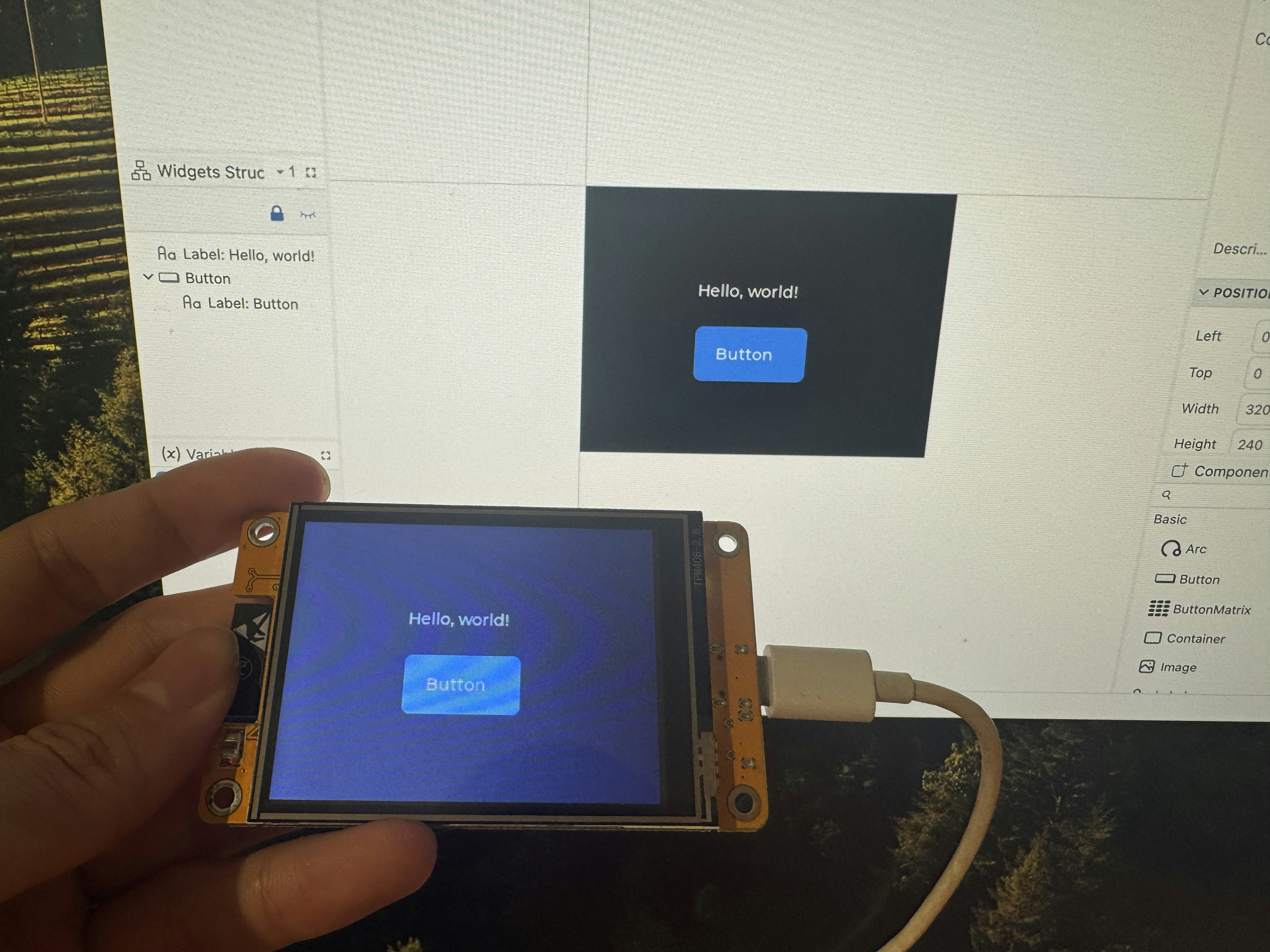
EZZ studioでデザインする
- EEZ Studioを起動し、テンプレートから**「LVGL」**を選択します。
※「LVGL with EEZ Flow」ではないので注意 - PROJECT SETTINGから**名前とLVGLバージョン(9.x)**を選択して作成

設定(歯車アイコン):
-
Setting > Build
LVGL include を lvgl/lvgl.h → lvgl.h に変更 -
Setting > General
Display Width:320
Display Height:240
Dark Theme:背景を暗くしたい場合はチェックを入れる -
画面サイズの設定:
編集画面に戻り、Properties > POSITION AND SIZE から画面サイズを指定 -
GUIコンポーネントの作成:
画面右下の Components Palette からパーツを配置可能 - Buildボタン(歯車横)をクリックすると、ビルドされてフォルダに出力されます

プロジェクトのルートへ反映する
ビルドされたファイルをプロジェクトのルートディレクトリへコピーします。
メインファイルを作成する
プロジェクトに必要な inoファイル や初期化コードなどを記述して、ESP32上で実行できるように整えていきます。
/*
 * eez studioで作成したUIデザインをESP32のTFT_eSPIで表示するサンプル
 */

// LVGLライブラリのインクルード
#include <lvgl.h>

// TFT_eSPIライブラリのインクルード
#include <TFT_eSPI.h>

// タッチスクリーンライブラリのインクルード
#include <XPT2046_Touchscreen.h>

// eez studioで生成されたUIファイルのインクルード
#include "ui.h"

// タッチスクリーンピンの定義
#define XPT2046_IRQ 36   // T_IRQ
#define XPT2046_MOSI 32  // T_DIN
#define XPT2046_MISO 39  // T_OUT
#define XPT2046_CLK 25   // T_CLK
#define XPT2046_CS 33    // T_CS

SPIClass touchscreenSPI = SPIClass(VSPI);
XPT2046_Touchscreen touchscreen(XPT2046_CS, XPT2046_IRQ);

// 画面サイズの定義
#define SCREEN_WIDTH 240
#define SCREEN_HEIGHT 320

// タッチスクリーン座標と圧力
int x, y, z;

// LVGL描画バッファの設定
#define DRAW_BUF_SIZE (SCREEN_WIDTH * SCREEN_HEIGHT / 10 * (LV_COLOR_DEPTH / 8))
uint32_t draw_buf[DRAW_BUF_SIZE / 4];

// LVGLのログ出力関数
void log_print(lv_log_level_t level, const char * buf) {
  LV_UNUSED(level);
  Serial.println(buf);
  Serial.flush();
}

// タッチスクリーンからの入力を読み取る関数
void touchscreen_read(lv_indev_t * indev, lv_indev_data_t * data) {
  if(touchscreen.tirqTouched() && touchscreen.touched()) {
    TS_Point p = touchscreen.getPoint();

    // タッチ座標のマッピングを調整(画面サイズに収まるように境界をチェック)
    int raw_x = p.y;
    int raw_y = p.x;

    // キャリブレーション値を調整(実際のハードウェアに合わせて)
    x = map(raw_x, 240, 3800, 0, SCREEN_WIDTH);
    y = map(raw_y, 200, 3700, 0, SCREEN_HEIGHT);

    // 境界チェック(画面の範囲を超えないようにする)
    if (x < 0) x = 0;
    if (x >= SCREEN_WIDTH) x = SCREEN_WIDTH - 1;
    if (y < 0) y = 0;
    if (y >= SCREEN_HEIGHT) y = SCREEN_HEIGHT - 1;

    z = p.z;

    // デバッグ情報の出力
    Serial.print("Touch X = ");
    Serial.print(x);
    Serial.print(" | Y = ");
    Serial.print(y);
    Serial.print(" | Raw X = ");
    Serial.print(raw_x);
    Serial.print(" | Raw Y = ");
    Serial.print(raw_y);
    Serial.print(" | Original X = ");
    Serial.print(p.x);
    Serial.print(" | Original Y = ");
    Serial.println(p.y);

    data->state = LV_INDEV_STATE_PRESSED;
    data->point.x = x;
    data->point.y = y;
  }
  else {
    data->state = LV_INDEV_STATE_RELEASED;
  }
}

void setup() {
  // シリアル通信の開始
  Serial.begin(115200);
  String LVGL_Arduino = String("LVGL Library Version: ") + lv_version_major() + "." + lv_version_minor() + "." + lv_version_patch();
  Serial.println(LVGL_Arduino);

  // LVGLの初期化
  lv_init();

  // デバッグ用のログ出力関数の登録
  lv_log_register_print_cb(log_print);

  // タッチスクリーンのSPI初期化と設定
  touchscreenSPI.begin(XPT2046_CLK, XPT2046_MISO, XPT2046_MOSI, XPT2046_CS);
  touchscreen.begin(touchscreenSPI);
  // タッチスクリーンの回転設定を調整
  touchscreen.setRotation(1);  // 0, 1, 2, 3の値を試してみてください

  // ディスプレイオブジェクトの作成
  lv_display_t * disp;
  disp = lv_tft_espi_create(SCREEN_WIDTH, SCREEN_HEIGHT, draw_buf, sizeof(draw_buf));

  // ディスプレイの回転設定を調整 - 90度回転
  lv_display_set_rotation(disp, LV_DISPLAY_ROTATION_90);

  // LVGLの入力デバイス(タッチスクリーン)の初期化
  lv_indev_t * indev = lv_indev_create();
  lv_indev_set_type(indev, LV_INDEV_TYPE_POINTER);
  lv_indev_set_read_cb(indev, touchscreen_read);

  // eez studioで生成されたUIの初期化
  ui_init();
}

void loop() {
  lv_task_handler();  // GUIの処理
  ui_tick();          // eez studioのUIの更新
  lv_tick_inc(5);     // LVGLに経過時間を通知
  delay(5);           // 遅延
}
ビルドする
ビルドが完了したら、ESP32に書き込みます。
表示結果

参考