Arduinoを使って、5つのチャンネル(CH0からCH4)の信号を生成するコードについて解説します。このプロジェクトは、基準信号(CH0)と4つの制御機器(CH1〜CH4)を制御するためのもので、シンプルながらも実用的なタイミング制御の例となります。
概要
このコードは、以下の機能を実現します:
- 基準信号(CH0)を生成
- 4つの異なる制御機器(CH1〜CH4)のオン・オフを制御
各チャンネルのピンは次のように定義されています:
-
CH0: 基準信号用ピン -
CH1: 制御機器1用ピン -
CH2: 制御機器2用ピン -
CH3: 制御機器3用ピン -
CH4: 制御機器4用ピン
コードの詳細
ピンの設定
最初に、各チャンネルのピンを定義し、setup関数内でこれらを出力モードに設定します。
const int CH0 = 13;  // 基準信号用ピン
const int CH1 = 12;  // 制御機器1用ピン
const int CH2 = 4;  // 制御機器2用ピン
const int CH3 = 5;  // 制御機器3用ピン
const int CH4 = 6;  // 制御機器4用ピン

void setup() {
  pinMode(CH0, OUTPUT);
  pinMode(CH1, OUTPUT);
  pinMode(CH2, OUTPUT);
  pinMode(CH3, OUTPUT);
  pinMode(CH4, OUTPUT);
}
信号生成のループ
loop関数では、各スロットに対して以下の順序で信号を生成します:
- 制御機器チャンネルのオン
- 基準信号のオン
- 基準信号のオフ
- 制御機器チャンネルのオフ
void loop() {
  for (int slot = 0; slot < 4; slot++) {

    // 制御機器チャンネルのオン
    if (slot == 0) digitalWrite(CH1, HIGH);
    if (slot == 1) digitalWrite(CH2, HIGH);
    if (slot == 2) digitalWrite(CH3, HIGH);
    if (slot == 3) digitalWrite(CH4, HIGH);

    // 基準信号のオン待機
    delayMicroseconds(20);

    // 基準信号のオン
    digitalWrite(CH0, HIGH);
    delayMicroseconds(100);
    // 基準信号のオフ
    digitalWrite(CH0, LOW);

    // 制御機器チャンネルのオフ待機
    delayMicroseconds(20);

    // 制御機器チャンネルのオフ
    if (slot == 0) digitalWrite(CH1, LOW);
    if (slot == 1) digitalWrite(CH2, LOW);
    if (slot == 2) digitalWrite(CH3, LOW);
    if (slot == 3) digitalWrite(CH4, LOW);

    // スロットの残り時間を待機
    delayMicroseconds(30);
  }
}
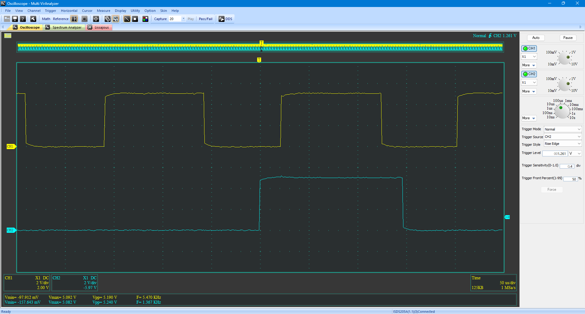
実行結果
CH0 (オシロスコープではCH1) とCH1(オシロスコープではCH2)の波形
全体コード
const int CH0 = 13;  // カメラシャッター用ピン
const int CH1 = 12;  // 照明1用ピン
const int CH2 = 4;  // 照明2用ピン
const int CH3 = 5;  // 照明3用ピン
const int CH4 = 6;  // 照明4用ピン

void setup() {
  pinMode(CH0, OUTPUT);
  pinMode(CH1, OUTPUT);
  pinMode(CH2, OUTPUT);
  pinMode(CH3, OUTPUT);
  pinMode(CH4, OUTPUT);
}


void loop() {
  for (int slot = 0; slot < 4; slot++) {

    // Light CH1~4 watit
    // delayMicroseconds(10);

    if (slot == 0) digitalWrite(CH1, HIGH);
    if (slot == 1) digitalWrite(CH2, HIGH);
    if (slot == 2) digitalWrite(CH3, HIGH);
    if (slot == 3) digitalWrite(CH4, HIGH);

    // Cam CH0 wait
    delayMicroseconds(20);

     // CH0をHighに設定
    digitalWrite(CH0, HIGH);
    // CH0の残りのON時間
    delayMicroseconds(100);
    // CH0をLOWに設定
    digitalWrite(CH0, LOW);

    // 照明チャンネルの残りのON時間
    delayMicroseconds(20);

    // アクティブな照明チャンネルをLOWに設定
    if (slot == 0) digitalWrite(CH1, LOW);
    if (slot == 1) digitalWrite(CH2, LOW);
    if (slot == 2) digitalWrite(CH3, LOW);
    if (slot == 3) digitalWrite(CH4, LOW);

    // スロットの残り時間を待機
    delayMicroseconds(30);
  }
}
結論
このコードは、Arduinoを使って複数のチャンネルの信号を制御する基本的な方法を示しています。基準信号と複数の制御機器を同期して制御することで、様々な応用が可能です。Arduinoの出力ピンを適切に設定し、タイミング制御を工夫することで、多様な信号制御が実現できます。