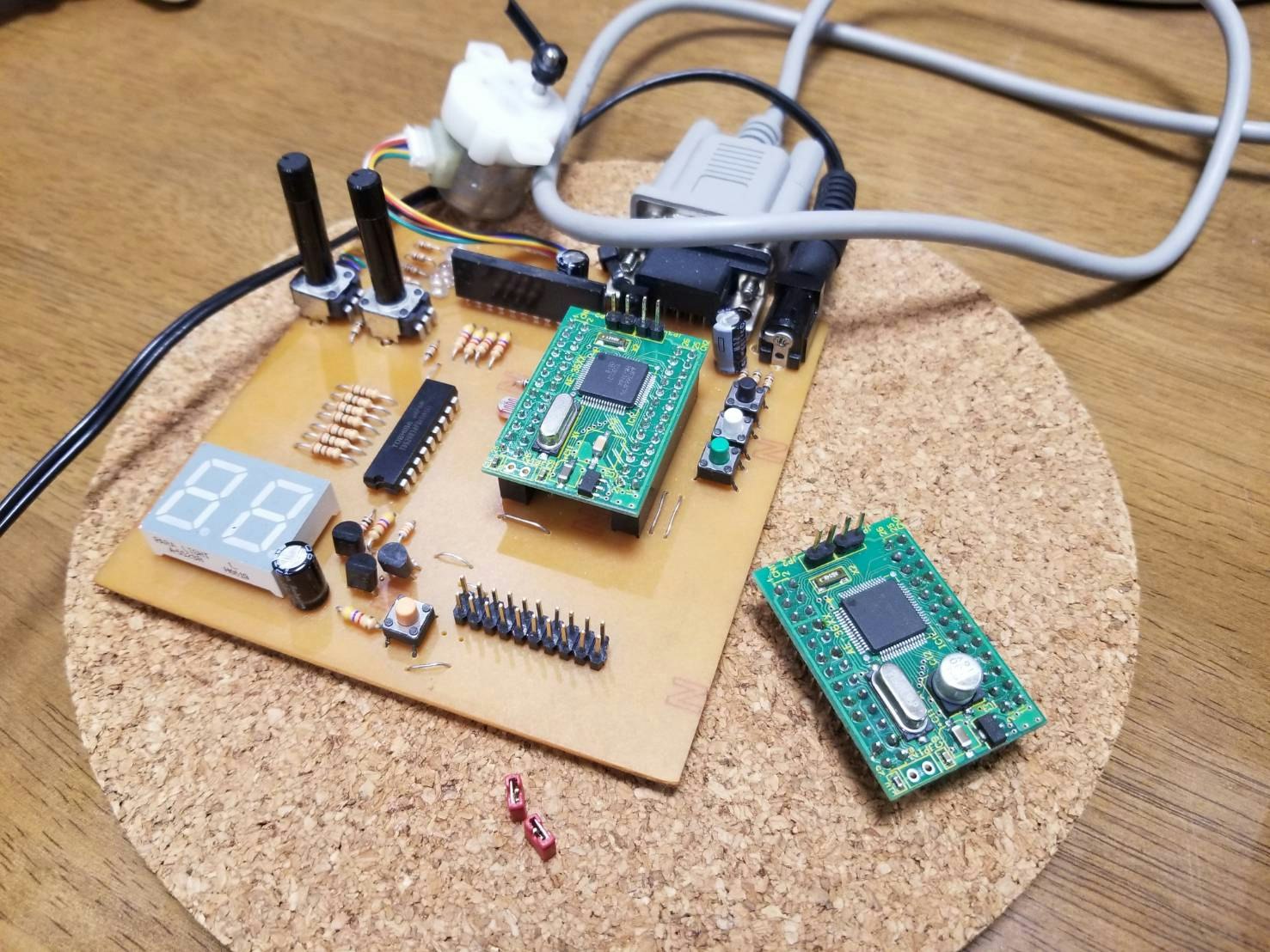
年末年始の時間を使いH8/3664を使ってマイコン制御に挑戦してみました。
使ったマイコンはルネサステクノロジフラッシュマイコンH8/3664F
開発環境はYellowIDE5 です。
//押しボタンで任意の数字を表示するプログラム
//#include <H83664.H>
# include <stdio.h>

# define	BRR		(*((unsigned char *)0xFFA9))
# define	TMA		(*((unsigned char *)0xFFA6))

# define	PMR1	(*((unsigned char *)0xFFE0))
# define	PMR5	(*((unsigned char *)0xFFE1))

# define	PCR1	(*((unsigned char *)0xFFE4))
# define	PCR5	(*((unsigned char *)0xFFE8))
# define	PCR7	(*((unsigned char *)0xFFEA))
# define	PCR8	(*((unsigned char *)0xFFEB))

# define	PDR5	(*((unsigned char *)0xFFD8))
# define	PDR7	(*((unsigned char *)0xFFDA))

main()
   {
	BRR=12;			//16MHZ時には12を デフォルトは7 ボーレート変更
 	PMR1 = 0x00;			/*ポート1を汎用IOに設定*/
 	PMR5 = 0x00;			/*ポート1を汎用IOに設定*/

    TMA = 0x98 ;


 	PCR1 = 0xff;	//アドレス FFE4
   	PCR5 = 0xff;	//FFE8
	PCR7 = 0x00;
    PCR8 = 0xff;	//FFED		//00入力  ff出力


for (;;) {/* 無限ループ */
    if ((PDR7 & 0x40)==0x00) PDR5 = 0x06;//黒 1
    else if((PDR7 & 0x20)==0x00) PDR5 = 0x5b;//白 2
    else if((PDR7 & 0x10)==0x00) PDR5 = 0x4f;//緑 3
    else PDR5 = 0x3f;//0
}
return 0;

   }
プログラムはこのようになります。
文頭の定義文です。
# define	BRR		(*((unsigned char *)0xFFA9))
# define	TMA		(*((unsigned char *)0xFFA6))

# define	PMR1	(*((unsigned char *)0xFFE0))
# define	PMR5	(*((unsigned char *)0xFFE1))

# define	PCR1	(*((unsigned char *)0xFFE4))
# define	PCR5	(*((unsigned char *)0xFFE8))
# define	PCR7	(*((unsigned char *)0xFFEA))
# define	PCR8	(*((unsigned char *)0xFFEB))

# define	PDR5	(*((unsigned char *)0xFFD8))
# define	PDR7	(*((unsigned char *)0xFFDA))
私の開発環境ではH83664.Hの中にまとめて定義されているのですが、
すべての開発環境に同じヘッダファイルがあるとは限らないので今回はあえて直接定義しています。
数値としてよりもビットに意味を持たせることが多いので、符号なし整数をつかいました。
例えば、BRRは、FFA9番地のバイト領域です。
C言語で「0xFFA9」は、単なる整数なのでキャスト演算子
(unsigned char *)0xFFA9
により、バイト領域へのポインタに型変換をおこないます。
これで「0xFFA9番地のバイト領域」を指すポインタができるので続いて、このメモリ領域にアクセスするには、
*((unsigned char *)0xFFA9)
と「参照演算子(*)」を使います。
今回使用する主なレジスタは
PMR:ポートモードレジスタ
同じピンでも、他の機能と兼用になっているピンがあるためその切り替えをこのレジスタで設定します。
入出力ポート:0
その他の目的のために端子を使う:1
(デフォルト:1)
PCR:ポートコントロールレジスタ
I/Oポートで、入力か出力かを設定します
出力:1
入力:0
(デフォルト:1)
PDR:ポートデータレジスタ
データのやり取りをするポートです。
(デフォルト:1)
です。
プッシュスイッチ
今回押しボタンはP76 P75 P74を用いています。
if ((PDR7 & 0x40)==0x00) PDR5 = 0x06;//黒 1
    else if((PDR7 & 0x20)==0x00) PDR5 = 0x5b;//白 2
    else if((PDR7 & 0x10)==0x00) PDR5 = 0x4f;//緑 3
    else PDR5 = 0x3f;//0
押されると各Port下一桁のビットが0となるのでP76が押された時は
(1011 1111)&(0100 0000)=0000 0000
とすべて0となるようにしています。
7segLED
7segLEDはP5xを使っています。
PDR5は7segLEDにつながるレジスタです。
7segLEDは下図のようになっております。
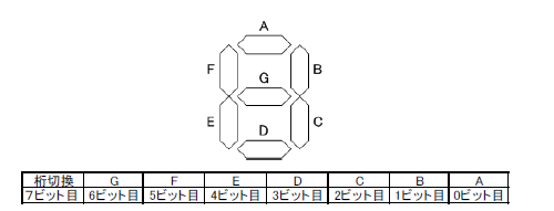
今回使用した7segLEDは二桁表示でhは1の桁10の桁どちらを点灯させるか選ぶことができます。
1の位に出す場合
0 PDR5 =0x3f
1 PDR5 =0x06
2 PDR5 =0x5b
3 PDR5 =0x4f
4 PDR5 =0x66
5 PDR5 =0x6d
6 PDR5 =0x7d
7 PDR5 =0x27
8 PDR5 =0x7f
9 PDR5 =0x67
LED[] = {0x3f,0x06,0x5b,0x4f,0x66,0x6d,0x7d,0x27,0x7f,0x67};
0 PDR5 =00111111
1 PDR5 =00000110
2 PDR5 =01011011
3 PDR5 =01001111
4 PDR5 =01100110
5 PDR5 =01101101
6 PDR5 =01111101
7 PDR5 =00100111
8 PDR5 =01111111
9 PDR5 =01100111
10の位に出したいときは8bit目を1にすればよいです。