もうずいぶん前になりますが電子工作系のハッカソンで作ったフルカラーLEDコントローラーを
ESP32 C3 で作り直してみました。
ハッカソンの時は
ESP32が販売されていなかったのでWROOM-02を使っていました。
またこの基板はWS2812BタイプのフルカラーLEDチューブに対応しています。
コチラが回路図です。

DIP SWはID設定用でWiFiでコントロールする際、複数のボードを制御できるようにするために設置しています。
LED2、SW4は自由にお使いいただけます。
LEDチューブはAmazonやAlliexpressで購入できます。
プログラムの開発は Arduino IDEで出来ます。
Arduino IDE で ESP32系のマイコンを使えるように設定します。
(既にESP32系のマイコンが使えるようになっている場合は不要です)
ファイル -> 環境設定 から 環境設定画面を開きます

追加のボードマネージャーのURLに
https://raw.githubusercontent.com/espressif/arduino-esp32/gh-pages/package_esp32_index.json
を追加します。
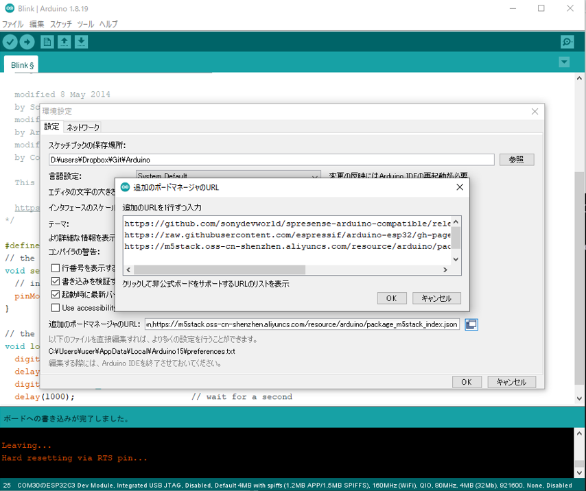
追加が終わったら環境設定画面を閉じてください。
次に ツール から ボードマネージャーを開きます

検索欄に ESP32 と入力します。
(この画像では既にインストールされているので インストールボタン を押せませんが<、インストールしていない場合はボタンを押せますので インストールしてください。)

これで Arduino IDE へのESP32系の開発環境のセットアップは終了です。
Arduino IDE で ESP32系のマイコンが選択できるようになっているはずです。

今回のLEDコントローラーボードは 上の画像の
ESP32 C3 Dev Moduleを使います。
次にこのボードにプログラムを書き込みます。
写真のようにCN4にマイクロBコネクターで、パソコンやモバイルバッテリーから電源を供給します。
緑のPower LED(LED 1)が点灯します。

次にCN3とパソコンのUSBコネクターを接続します。
(この基板はプログラミング用と電源供給用の2本のケーブルが必要となっています)
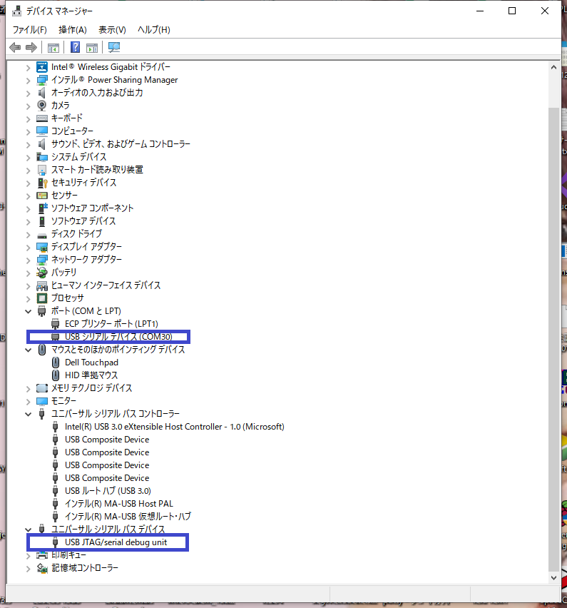
CN3とパソコンを接続すると自動ででデバイスライバーがインストールされます。
(ただし初めて接続する場合や途中でArduino IDEがボードを認識しなくなった場合、書き込み時にエラーが発生する場合は BOOT SW を押しながら電源を供給してください。)
パソコンがボードを認識するとデバイスドライバーの確認画面に次の画像のように
USBシリアルデバイス(COMXX)
USB JTAG/serial debug unit
が表示されます。
次に基板動作確認とプログラミングの確認に 定番の Blink プログラムを書いてみます。
Blinkプログラムは
スケッチ例 -> 01.Basicsの中にあります。

プログラムのLED_BUILTINの定義だけ変更します。
ボード上のLED2 はIO3に接続されているので以下のように変更します。
/*
  Blink

  Turns an LED on for one second, then off for one second, repeatedly.

  Most Arduinos have an on-board LED you can control. On the UNO, MEGA and ZERO
  it is attached to digital pin 13, on MKR1000 on pin 6. LED_BUILTIN is set to
  the correct LED pin independent of which board is used.
  If you want to know what pin the on-board LED is connected to on your Arduino
  model, check the Technical Specs of your board at:
  https://www.arduino.cc/en/Main/Products

  modified 8 May 2014
  by Scott Fitzgerald
  modified 2 Sep 2016
  by Arturo Guadalupi
  modified 8 Sep 2016
  by Colby Newman

  This example code is in the public domain.

  https://www.arduino.cc/en/Tutorial/BuiltInExamples/Blink
*/

#define LED_BUILTIN 3     // IO3
// the setup function runs once when you press reset or power the board
void setup() {
  // initialize digital pin LED_BUILTIN as an output.
  pinMode(LED_BUILTIN, OUTPUT);
}

// the loop function runs over and over again forever
void loop() {
  digitalWrite(LED_BUILTIN, LOW);    // turn the LED on (HIGH is the voltage level)
  delay(1000);                       // wait for a second
  digitalWrite(LED_BUILTIN, LOW);    // turn the LED off by making the voltage LOW
  delay(1000);                       // wait for a second
}
ボードが壊れていない、かつプログラムが正しく書き込まれたなら**LED2(青)**が1秒毎に点滅します。
次にArduino IDE にLEDチューブ用のライブラリを追加します。
ライブラリマネージャーからインストールできます。
スケッチ->ライブラリをインクルード->ライブラリを管理 から
検索欄に neopixel と入力すると3つの候補が表示されるので
Adafruit NeoPixel を選択してインストールします。

ライブラリのインストールが正常に行われると スケッチ例 の中に Adafruit NeoPixel が追加されます。

この中の strandtest を動かしてみます。
コントロールボードとLEDは CN1 で接続します。
#define LED_PIN 6
を
#define LED_PIN 5 に変更します。
#define LED_COUNT 60 の60はLEDの数に合わせます。
// A basic everyday NeoPixel strip test program.

// NEOPIXEL BEST PRACTICES for most reliable operation:
// - Add 1000 uF CAPACITOR between NeoPixel strip's + and - connections.
// - MINIMIZE WIRING LENGTH between microcontroller board and first pixel.
// - NeoPixel strip's DATA-IN should pass through a 300-500 OHM RESISTOR.
// - AVOID connecting NeoPixels on a LIVE CIRCUIT. If you must, ALWAYS
//   connect GROUND (-) first, then +, then data.
// - When using a 3.3V microcontroller with a 5V-powered NeoPixel strip,
//   a LOGIC-LEVEL CONVERTER on the data line is STRONGLY RECOMMENDED.
// (Skipping these may work OK on your workbench but can fail in the field)

#include <Adafruit_NeoPixel.h>
#ifdef __AVR__
 #include <avr/power.h> // Required for 16 MHz Adafruit Trinket
#endif

// Which pin on the Arduino is connected to the NeoPixels?
// On a Trinket or Gemma we suggest changing this to 1:
#define LED_PIN    5

// How many NeoPixels are attached to the Arduino?
#define LED_COUNT 60

// Declare our NeoPixel strip object:
Adafruit_NeoPixel strip(LED_COUNT, LED_PIN, NEO_GRB + NEO_KHZ800);
// Argument 1 = Number of pixels in NeoPixel strip
// Argument 2 = Arduino pin number (most are valid)
// Argument 3 = Pixel type flags, add together as needed:
//   NEO_KHZ800  800 KHz bitstream (most NeoPixel products w/WS2812 LEDs)
//   NEO_KHZ400  400 KHz (classic 'v1' (not v2) FLORA pixels, WS2811 drivers)
//   NEO_GRB     Pixels are wired for GRB bitstream (most NeoPixel products)
//   NEO_RGB     Pixels are wired for RGB bitstream (v1 FLORA pixels, not v2)
//   NEO_RGBW    Pixels are wired for RGBW bitstream (NeoPixel RGBW products)


// setup() function -- runs once at startup --------------------------------

void setup() {
  // These lines are specifically to support the Adafruit Trinket 5V 16 MHz.
  // Any other board, you can remove this part (but no harm leaving it):
#if defined(__AVR_ATtiny85__) && (F_CPU == 16000000)
  clock_prescale_set(clock_div_1);
#endif
  // END of Trinket-specific code.

  strip.begin();           // INITIALIZE NeoPixel strip object (REQUIRED)
  strip.show();            // Turn OFF all pixels ASAP
  strip.setBrightness(50); // Set BRIGHTNESS to about 1/5 (max = 255)
}


// loop() function -- runs repeatedly as long as board is on ---------------

void loop() {
  // Fill along the length of the strip in various colors...
  colorWipe(strip.Color(255,   0,   0), 50); // Red
  colorWipe(strip.Color(  0, 255,   0), 50); // Green
  colorWipe(strip.Color(  0,   0, 255), 50); // Blue

  // Do a theater marquee effect in various colors...
  theaterChase(strip.Color(127, 127, 127), 50); // White, half brightness
  theaterChase(strip.Color(127,   0,   0), 50); // Red, half brightness
  theaterChase(strip.Color(  0,   0, 127), 50); // Blue, half brightness

  rainbow(10);             // Flowing rainbow cycle along the whole strip
  theaterChaseRainbow(50); // Rainbow-enhanced theaterChase variant
}


// Some functions of our own for creating animated effects -----------------

// Fill strip pixels one after another with a color. Strip is NOT cleared
// first; anything there will be covered pixel by pixel. Pass in color
// (as a single 'packed' 32-bit value, which you can get by calling
// strip.Color(red, green, blue) as shown in the loop() function above),
// and a delay time (in milliseconds) between pixels.
void colorWipe(uint32_t color, int wait) {
  for(int i=0; i<strip.numPixels(); i++) { // For each pixel in strip...
    strip.setPixelColor(i, color);         //  Set pixel's color (in RAM)
    strip.show();                          //  Update strip to match
    delay(wait);                           //  Pause for a moment
  }
}

// Theater-marquee-style chasing lights. Pass in a color (32-bit value,
// a la strip.Color(r,g,b) as mentioned above), and a delay time (in ms)
// between frames.
void theaterChase(uint32_t color, int wait) {
  for(int a=0; a<10; a++) {  // Repeat 10 times...
    for(int b=0; b<3; b++) { //  'b' counts from 0 to 2...
      strip.clear();         //   Set all pixels in RAM to 0 (off)
      // 'c' counts up from 'b' to end of strip in steps of 3...
      for(int c=b; c<strip.numPixels(); c += 3) {
        strip.setPixelColor(c, color); // Set pixel 'c' to value 'color'
      }
      strip.show(); // Update strip with new contents
      delay(wait);  // Pause for a moment
    }
  }
}

// Rainbow cycle along whole strip. Pass delay time (in ms) between frames.
void rainbow(int wait) {
  // Hue of first pixel runs 5 complete loops through the color wheel.
  // Color wheel has a range of 65536 but it's OK if we roll over, so
  // just count from 0 to 5*65536. Adding 256 to firstPixelHue each time
  // means we'll make 5*65536/256 = 1280 passes through this loop:
  for(long firstPixelHue = 0; firstPixelHue < 5*65536; firstPixelHue += 256) {
    // strip.rainbow() can take a single argument (first pixel hue) or
    // optionally a few extras: number of rainbow repetitions (default 1),
    // saturation and value (brightness) (both 0-255, similar to the
    // ColorHSV() function, default 255), and a true/false flag for whether
    // to apply gamma correction to provide 'truer' colors (default true).
    strip.rainbow(firstPixelHue);
    // Above line is equivalent to:
    // strip.rainbow(firstPixelHue, 1, 255, 255, true);
    strip.show(); // Update strip with new contents
    delay(wait);  // Pause for a moment
  }
}

// Rainbow-enhanced theater marquee. Pass delay time (in ms) between frames.
void theaterChaseRainbow(int wait) {
  int firstPixelHue = 0;     // First pixel starts at red (hue 0)
  for(int a=0; a<30; a++) {  // Repeat 30 times...
    for(int b=0; b<3; b++) { //  'b' counts from 0 to 2...
      strip.clear();         //   Set all pixels in RAM to 0 (off)
      // 'c' counts up from 'b' to end of strip in increments of 3...
      for(int c=b; c<strip.numPixels(); c += 3) {
        // hue of pixel 'c' is offset by an amount to make one full
        // revolution of the color wheel (range 65536) along the length
        // of the strip (strip.numPixels() steps):
        int      hue   = firstPixelHue + c * 65536L / strip.numPixels();
        uint32_t color = strip.gamma32(strip.ColorHSV(hue)); // hue -> RGB
        strip.setPixelColor(c, color); // Set pixel 'c' to value 'color'
      }
      strip.show();                // Update strip with new contents
      delay(wait);                 // Pause for a moment
      firstPixelHue += 65536 / 90; // One cycle of color wheel over 90 frames
    }
  }
}
これでLEDがカラフルに光りだします。

最初にも書きましたがこのボードはWiFiやBLEに対応していますので色々な使い方が出来ます。
例えばキーボード(楽器)とBLEで接続してLEDをキーボードでコントロールしたりとか。

現在サンプルを準備中です。