pico-examplesには気圧センサBME280(SPIバス)のコードが入っています。BMP280はその前のモデルに当たり、温度と気圧が測れます。内部のレジスタはBME280と同じで、湿度関連が省略されています。したがって、BME280のコードから湿度関連を削除し、SPIバスのアクセスをI2Cバス用に書き換えます。
開発環境はラズパイ4です。入れ忘れているかもしれないのでToolchainをインストールします。
sudo apt install cmake gcc-arm-none-eabi libnewlib-arm-none-eabi build-essential
標準出力を用意
最初に、printfの出力先を用意します。
https://datasheets.raspberrypi.org/pico/getting-started-with-pico.pdf
の「Chapter 4. Saying "Hello World" in C」を実行できるようにします。すでにbiuldされたコードがありました。通信用ソフトminicomもインストールされていました。raspi-configで行うUARTの変更もすんでいます。
次のようにUARTを接続します。
| Pico UART0名称 | Pico 物理的ピン番号 | Pico GPIOピン番号 | ラズパイの物理ピン番号 |
|---|---|---|---|
| GND | 3 | GND | 6(GND) |
| UART0_TX | 1 | GP0 | 10(Rx) |
| UART0_RX | 2 | GP1 | 8(Tx) |
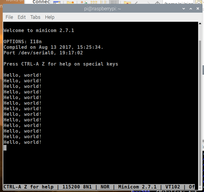
ターミナルを一つ立ち上げて、次のコマンドで通信ソフトを動かします。
minicom -b 115200 -o -D /dev/serial0
BOOTSELボタンを押したままUSBケーブルをつなげます。つながったら、BOOTSELから手を放します。RPI-RP2ドライブがマウントされます。
pico\pico-examples\build\hello_world\serialに入っているhello_serial.uf2を、デスクトップに表示されているRPI-RP2ドライブにドラッグします。
minicomの動いているターミナルに、文字が表示されたことを確認します。このままターミナルで通信ソフトは動かしたままにします。
BMP280の接続
AdafruitのSTEMMA QTのBMP280を使います。I2Cで使うようにコネクタがついています。ほかのボードでもかまいません。ジャンパなどがあればI2Cバスを有効にします。このボードはスレーブ・アドレスが0x77に設定されています。入手したボードが0x76の場合は、該当部分を変更してください。

ケーブルの色は自作なので、白色の代わりに黄色になっています。ほかのピンは純正(Adafruit)と同じ色です。
| STEMMA QTコネクタ | 物理的ピン番号 | GPIOピン番号 |
|---|---|---|
| SCL 緑 | 12 | GP9 |
| SDA 黄 | 11 | GP8 |
| Vcc 赤 | ラズパイの3.3Vへ | - |
| GND 黒 | ラズパイのGNDへ | - |
pico/pico-examples/i2c/bus_scanに入っているbus_scan.cのピン番号を変更します。
int main() {
    // Enable UART so we can print status output
    stdio_init_all();

    // This example will use I2C0 on GPIO4 (SDA) and GPIO5 (SCL)
    i2c_init(i2c0, 100 * 1000);
    gpio_set_function(8, GPIO_FUNC_I2C);
    gpio_set_function(9, GPIO_FUNC_I2C);
    gpio_pull_up(8);
    gpio_pull_up(9);
makefileはすでにできているので、cmakeは動かしません。
/home/pi/pico/pico-examples/build/i2c/bus_scanに移動して、
make -j4
します。
BOOTSELボタンを押したままUSBケーブルをつなげます(抜き差し)。
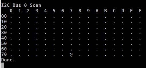
pico\pico-examples\build\i2c\bus_scanに入っているi2c_bus_scan.uf2を、デスクトップに表示されているRPI-RP2ドライブにドラッグします。
minicomの動いているターミナルに、スレーブ・アドレスの0x77の位置に@が表示されたことを確認します。
BMP280のプログラム
I2Cバスなので、ソースは、/home/pi/pico/pico-examples/i2c/の中にbmp280_i2cフォルダを作り、bmp280_i2c.cのソースを入れました。隣のbus_scanのCMakeLists.txtをコピペし、内容を次のように変更し、保存します。つまり、このフォルダには、ソースのbmp280_i2c.c(最後に掲載)とCMakeLists.txtが存在します。
add_executable(bmp280_i2c
        bmp280_i2c.c
        )

# Pull in our (to be renamed) simple get you started dependencies
target_link_libraries(bmp280_i2c pico_stdlib hardware_i2c)

# create map/bin/hex file etc.
pico_add_extra_outputs(bmp280_i2c)

# add url via pico_set_program_url
example_auto_set_url(bmp280_i2c)
/home/pi/pico/pico-examples/build/i2cディレクトリで、cmake_install.cmakeのファイルを開き、endifの前に1行追加します。
if(NOT CMAKE_INSTALL_LOCAL_ONLY)
  # Include the install script for each subdirectory.
  include("/home/pi/pico/pico-examples/build/i2c/bus_scan/cmake_install.cmake")
  include("/home/pi/pico/pico-examples/build/i2c/lcd_1602_i2c/cmake_install.cmake")
  include("/home/pi/pico/pico-examples/build/i2c/mpu6050_i2c/cmake_install.cmake")
  include("/home/pi/pico/pico-examples/build/i2c/lcd_1602_i2c/cmake_install.cmake")
  include("/home/pi/pico/pico-examples/build/i2c/bmp280_i2c/cmake_install.cmake")
endif()
/home/pi/pico/pico-examples/buildで、
export PICO_SDK_PATH=../../pico-sdk
cmake ..
/home/pi/pico/pico-examples/build/i2c/bmp280_i2cの中にmakeファイルが作られます。
/home/pi/pico/pico-examples/build/i2c/bmp280_i2cディレクトリに移動して、
make -j4
を実行しビルドします。
BOOTSELボタンを押したままUSBケーブルをつなげます(抜き差し)。
pico\pico-examples\build\i2c\bmp280_i2cに入っているbmp280.uf2を、デスクトップに表示されているRPI-RP2ドライブにドラッグします。
ソースです。ベースはBME280(SPIバス用)です。
/**
* Copyright (c) 2020 Raspberry Pi (Trading) Ltd.
*
* SPDX-License-Identifier: BSD-3-Clause
*/
# include <stdio.h>
# include <string.h>
# include "pico/stdlib.h"
# include "hardware/i2c.h"
/* Example code to talk to a bmp280 temperature/pressure sensor.
NOTE: Ensure the device is capable of being driven at 3.3v NOT 5v. The Pico
GPIO (and therefor SPI) cannot be used at 5v.
GPIO 8 (pin 11)-> SDA on bmp280 board
GPIO 9 (pin 12)-> SCL on bmp280 board
3.3v (pin 3;6) -> VCC on bmp280 board
GND (pin 38) -> GND on bmp280 board
*/
static int addr = 0x77;
# define I2C_PORT i2c0
# define ID_register 0xd0
# define READ_BIT 0x80
int32_t t_fine;
uint16_t dig_T1;
int16_t dig_T2, dig_T3;
uint16_t dig_P1;
int16_t dig_P2, dig_P3, dig_P4, dig_P5, dig_P6, dig_P7, dig_P8, dig_P9;
/* The following compensation functions are required to convert from the raw ADC
data from the chip to something usable. Each chip has a different set of
compensation parameters stored on the chip at point of manufacture, which are
read from the chip at startup and used inthese routines.
*/
int32_t compensate_temp(int32_t adc_T) {
int32_t var1, var2, T;
var1 = ((((adc_T >> 3) - ((int32_t) dig_T1 << 1))) * ((int32_t) dig_T2)) >> 11;
var2 = (((((adc_T >> 4) - ((int32_t) dig_T1)) * ((adc_T >> 4) - ((int32_t) dig_T1))) >> 12) * ((int32_t) dig_T3))
>> 14;
t_fine = var1 + var2;
T = (t_fine * 5 + 128) >> 8;
return T;
}
uint32_t compensate_pressure(int32_t adc_P) {
int32_t var1, var2;
uint32_t p;
var1 = (((int32_t) t_fine) >> 1) - (int32_t) 64000;
var2 = (((var1 >> 2) * (var1 >> 2)) >> 11) * ((int32_t) dig_P6);
var2 = var2 + ((var1 * ((int32_t) dig_P5)) << 1);
var2 = (var2 >> 2) + (((int32_t) dig_P4) << 16);
var1 = (((dig_P3 * (((var1 >> 2) * (var1 >> 2)) >> 13)) >> 3) + ((((int32_t) dig_P2) * var1) >> 1)) >> 18;
var1 = ((((32768 + var1)) * ((int32_t) dig_P1)) >> 15);
if (var1 == 0)
return 0;
p = (((uint32_t) (((int32_t) 1048576) - adc_P) - (var2 >> 12))) * 3125;
if (p < 0x80000000)
p = (p << 1) / ((uint32_t) var1);
else
p = (p / (uint32_t) var1) * 2;
var1 = (((int32_t) dig_P9) * ((int32_t) (((p >> 3) * (p >> 3)) >> 13))) >> 12;
var2 = (((int32_t) (p >> 2)) * ((int32_t) dig_P8)) >> 13;
p = (uint32_t) ((int32_t) p + ((var1 + var2 + dig_P7) >> 4));
return p;
}
static void write_register(uint8_t reg, uint8_t data) {
uint8_t buf[2];
//buf[0] = reg & 0x7f; // remove read bit as this is a write
buf[0] = reg;
buf[1] = data;
i2c_write_blocking(I2C_PORT, addr, buf, 2, true);
}
static void read_registers(uint8_t reg, uint8_t *buf, uint16_t len) {
// For this particular device, we send the device the register we want to read
// first, then subsequently read from the device. The register is auto incrementing
// so we don't need to keep sending the register we want, just the first.
reg = reg | READ_BIT;
i2c_write_blocking(I2C_PORT, addr, ®, 1, true);
i2c_read_blocking(I2C_PORT, addr, buf, len, false);
}
/* This function reads the manufacturing assigned compensation parameters from the device */
void read_compensation_parameters() {
uint8_t buffer[26];
read_registers(0x88, buffer, 24);
dig_T1 = buffer[0] | (buffer[1] << 8);
dig_T2 = buffer[2] | (buffer[3] << 8);
dig_T3 = buffer[4] | (buffer[5] << 8);
dig_P1 = buffer[6] | (buffer[7] << 8);
dig_P2 = buffer[8] | (buffer[9] << 8);
dig_P3 = buffer[10] | (buffer[11] << 8);
dig_P4 = buffer[12] | (buffer[13] << 8);
dig_P5 = buffer[14] | (buffer[15] << 8);
dig_P6 = buffer[16] | (buffer[17] << 8);
dig_P7 = buffer[18] | (buffer[19] << 8);
dig_P8 = buffer[20] | (buffer[21] << 8);
dig_P9 = buffer[22] | (buffer[23] << 8);
}
static void bmp280_read_raw(int32_t *pressure, int32_t *temperature) {
uint8_t buffer[6];
read_registers(0xF7, buffer, 6);
// printf("\nraw PressureData = %d %d\n", buffer[0],buffer[1]);
*pressure = ((uint32_t) buffer[0] << 12) | ((uint32_t) buffer[1] << 4) | (buffer[2] >> 4);
*temperature = ((uint32_t) buffer[3] << 12) | ((uint32_t) buffer[4] << 4) | (buffer[5] >> 4);
// printf("\nraw Pressure = %d\n", pressure);
// printf("raw Temp. = %d\n", temperature);
}
int main() {
stdio_init_all();
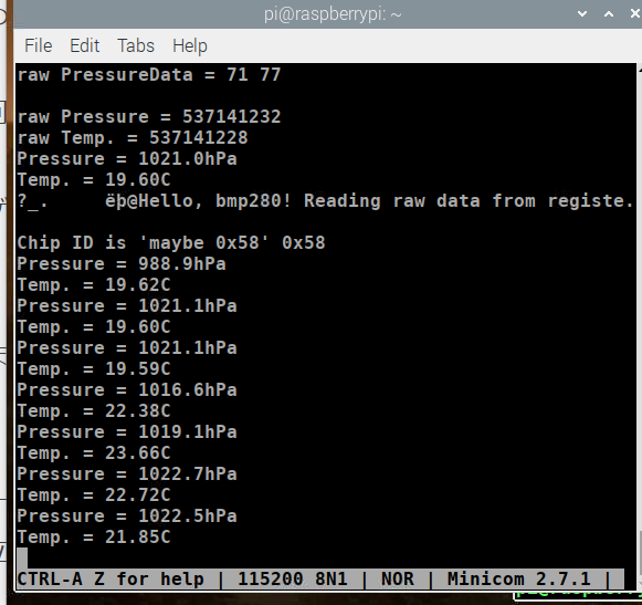
printf("Hello, bmp280! Reading raw data from registers via i2c...\n");
// This example will use I2C0 on GPIO8 (SDA) and GPIO9 (SCL) running at 100kHz.
i2c_init(I2C_PORT, 100 * 1000);
gpio_set_function(8, GPIO_FUNC_I2C);
gpio_set_function(9, GPIO_FUNC_I2C);
gpio_pull_up(8);
gpio_pull_up(9);
// interrograte the device for its I2C ID number, should be 0x58
uint8_t id;
read_registers(ID_register, &id, 1);
printf("\nChip ID is 'maybe 0x58' 0x%x\n", id);
read_compensation_parameters();
write_register(0xF5, 0x20);
write_register(0xF4, 0x27);// Set rest of oversampling modes and run mode to normal
int32_t pressure, temperature;
while (1) {
bmp280_read_raw(&pressure, &temperature);
// These are the raw numbers from the chip, so we need to run through the
// compensations to get human understandable numbers
pressure = compensate_pressure(pressure);
temperature = compensate_temp(temperature);
printf("Pressure = %.1fhPa\n", pressure / 100.0);
printf("Temp. = %.2fC\n", temperature / 100.0);
sleep_ms(5000);
}
return 0;
}