Picoには12ビット4チャネルのA-Dコンバータが内蔵されています。もし2チャネル足りなかったら、という想定で外部にICを追加します。
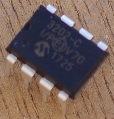
MCP3202のおもなスペック
- ビット数 12
- チャネル数 2(シングルエンド)、1(疑似差動)
- 基準電圧 内蔵なし、端子なし
- 変換速度 100ksps(5V時)
- インターフェース SPI(モード0,0および1,1)、クロック1.6MHz(5V時)、0.8MHz(2.7V時)
- 動作電圧 2.7~5.5V
- ピン数 8ピンDIP
接続
| MCP3202の端子 | Picoの端子(GPIO) | 名称 |
|---|---|---|
| 1 /CS | GP5 | SPI0 CSn |
| 2 ch0 | - | - |
| 3 ch1 | - | - |
| 4 Vss | GND | GND |
| 5 Din | GP3 | MOSI SPI0 Tx |
| 6 Dout | GP4 | MISO SPI0 RX |
| 7 CLK | GP2 | SPI0 SCK |
| 8 Vdd | 3V3 | 3.3V |
| 入力のch0には、電池駆動の簡易電源TL431の出力をつないでいます。約2.5Vです。ch1はGNDもしくは3.3Vにつないで結果をみます。 |
プログラムmcp3202.c
フォルダはmcp3202としました。CMakeLists.txtは省略します。17回以前を参考にしてください。
チャネルは、シングルエンドのch0、ch1、疑似差動のIN+/IN-、疑似差動のIN-/IN+から選択します。
コマンドを送るフォマットは次のとおりです(送るのはPicoで、送られてくるのもPicoです)。
Startbit チャネル指定2バイト MSBT
例えば、ch0であれば、
1 10 1
ch1であれば、
1 11 1
です。MSBTがMCP3202へ送られるタイミングで、1ビットおいて、
D11 D10 D9 D8 D7 D6 D5 D4 D3 D2 D1 D0
のA-D変換結果データが、MCP3202からPicoへ送られてきます。
SPIは基本8ビット単位なので、D0から前にさかのぼって、8ビット単位で送るべきデータを整理します。
x x x x x x x 1 1 1 0 1 x x x x x x x x x x x x
SPIはクロックを送り続けないとデータはやってきません。上記のxはダミーなので、0でも1でもかまいません。したがって、ここでは、ch0のデータは、次のようにしました。
0x01 0b11010000 0xff
3バイト送ったので、読み出したデータは3バイトです。1バイト目はごみなので捨てます。2バイト目は上位D11 D10 D9 D8が右詰めで入っています。3バイト目は、D7 D6 D5 D4 D3 D2 D1 D0です。
12ビットのデータなので、4096で割って、Vrefの3.3Vをかけて電圧を求めます。Vrefは、できるだけ正確にテスタで測った値を記入しておきます。
/**
 * Copyright (c) 2020 Raspberry Pi (Trading) Ltd.
 *
 * SPDX-License-Identifier: BSD-3-Clause
 */

# include <stdio.h>
# include <string.h>
# include "pico/stdlib.h"
# include "hardware/spi.h"

# define PIN_MISO 4
# define PIN_CS   5
# define PIN_SCK  2
# define PIN_MOSI 3

# define SPI_PORT spi0
static float Vref = 3.30;


static inline void cs_select() {
    asm volatile("nop \n nop \n nop");
    gpio_put(PIN_CS, 0);  // Active low
    asm volatile("nop \n nop \n nop");
}

static inline void cs_deselect() {
    asm volatile("nop \n nop \n nop");
    gpio_put(PIN_CS, 1);
    asm volatile("nop \n nop \n nop");
}

void setup_SPI(){
    // This example will use SPI0 at 0.5MHz.
    spi_init(SPI_PORT, 500 * 1000);
    gpio_set_function(PIN_MISO, GPIO_FUNC_SPI);
    gpio_set_function(PIN_SCK, GPIO_FUNC_SPI);
    gpio_set_function(PIN_MOSI, GPIO_FUNC_SPI);

    // Chip select is active-low, so we'll initialise it to a driven-high state
    gpio_init(PIN_CS);
    gpio_set_dir(PIN_CS, GPIO_OUT);
    gpio_put(PIN_CS, 1);
}

int readADC(uint8_t chData){
    uint8_t writeData[3] = {0x01, 0b10100000, 0xff};
    writeData[1] = chData;
    // printf("\n %b %b %b",writeData[0],writeData[1],writeData[2]);
    uint8_t buffer[3];
    cs_select();
    sleep_ms(1);
    spi_write_read_blocking(SPI_PORT, writeData, buffer, 3);
    sleep_ms(1);
    cs_deselect();

    return (buffer[1] & 0x0f) << 8 | buffer[2];
}

int main() {
    stdio_init_all();

    printf("\nHello, MCP3202 Reading raw data from registers via SPI...\n");

    setup_SPI();

    int dataCh0 = readADC(0b10100000);
    int dataCh1 = readADC(0b11100000);

    //printf(" %d %d \n", buffer[0], buffer[1]);
    // printf(" %b %b \n", (buffer[0] & 0b00011111)<<8, buffer[1]);
    //printf("%b %d \n",dataCh0, dataCh0);
    printf("\nch0 is %.4fV\n", Vref * dataCh0 / 4096);
    printf("ch1 is %.4fV\n", Vref * dataCh1 / 4096);
    return 0;
}
実行結果です。1回目ch1はGNDへ、2回目は3.3Vへつないでいます。
