背景
きっかけは忘れたけれど数年前に、歯車の数学が面白いということを知った。機構学と呼ばれる分野らしい。早速Amazonで教科書を購入した。・・・のだけど、部屋の隅っこに積んだままだった。最近身近にギアの話を聞く機会があったので、情熱が再燃した。
概要
理解したいのは、インボリュート歯車というもの。Wikipediaの当該項目を見てみると、面白い動画が載っているので是非観てほしい。
二つの歯車がかみ合って回転するとき、その角速度の比は、接触点の共通法線が、歯車の中心を結ぶ線分を横切る点と、それぞれの歯車の中心への距離に依存する(接触を保つ条件より)。言い換えれば、接触点の共通法線が一定でなければ(静止していなければ)、角速度が変化して滑らかに回転しないということである。
このような条件を満たす曲線として、インボリュート曲線がある。歯の形状がインボリュート曲線になっているような歯車をインボリュート歯車という。そこで、インボリュート曲線の基本的な数学を理解し、共通法線が一定である理由を理解し、さらに、Wikipediaにあるような、歯車が回転しても、法線が静止している様子をアニメーションにする。ここまで出来ればなんとなく理解できた気にはなりそう、というわけである。
インボリュート曲線とは
円に巻き付けられた糸を緩まないようにほどくと、糸の先端はインボリュート曲線を描く、らしい。
まず、半径$r$の円周上の点は、
\begin{aligned}
x &= r \cos\theta \\
y &= r \sin\theta
\end{aligned}
と書ける。
角度$\theta = 0$から糸をほどいていくとすると、角度$\theta$までほどいたときの糸の長さは、
r \theta
で与えられる。
糸が緩まないように引っ張ると、糸は円の法線方向を向く。
結局、糸の先端の座標は、
\boldsymbol{v} = r \boldsymbol{e}_r - r\theta \boldsymbol{e}_\theta
で与えられる。デカルト座標では、
\begin{aligned}
v_x &= r\cos\theta + r\theta\sin\theta \\
v_y &= r\sin\theta - r\theta\cos\theta
\end{aligned}
で与えられる。これがインボリュート曲線をあらわす式である。
インボリュート曲線を描いてみる
gnuplotを使って描いてみる。糸(インボリュート曲線の法線)はC言語でテキストファイルとして生成する。
#define _USE_MATH_DEFINES
#include <iostream>
#include <fstream>
#include <cmath>

int main()
{
    std::ofstream ofs("vec.txt");
    double r = 1;
    for (double t = 0; t < M_PI*0.6; t += 0.05)
    {
        ofs << r * cos(t) << " " << r * sin(t) << " " << r * t * sin(t) << " " << -r * t * cos(t) << std::endl;
    }
    return 0;
}
set style arrow 1 size 0.1
set notics
set size ratio -1
plot "vec.txt" with vector arrowstyle 1 t ""

r = 1.
set parametric
set trange [0:pi*0.6]
replot r*cos(t), r*sin(t) lw 2 t ""
replot r*cos(t)+r*t*sin(t), r*sin(t)-r*t*cos(t) lw 2 t ""
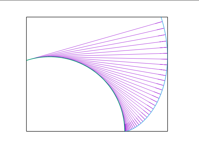
外側の緑色の曲線がインボリュート曲線である。これを見るとわかるのは、インボリュート曲線の法線は常に円(基礎円という)の接線となっていることである。
さて、あまり本質ではないのだが、アニメーションにするためには、インボリュート曲線を回転させる必要がある。そこで角度$\theta_0$から糸をほどくことにする。$\theta_0$から$\theta$を測ることにすれば、
\begin{align}
v_x &= r\cos(\theta+\theta_0) + r\theta\sin(\theta+\theta_0) \\
v_y &= r\sin(\theta+\theta_0) - r\theta\cos(\theta+\theta_0)
\end{align}
となる。
さらに、歯の反対側はインボリュート曲線が反転した形になっている。これを実現するには、$\theta \to -\theta$とすればよい。
2つのインボリュート曲線の共通法線
インボリュート曲線の法線は基礎円の接線となるのであった。それでは、基礎円をふたつ用意してふたつのインボリュート曲線を一点で接触させたらどうなるだろう。2曲線が接する場合、接線は共通となるため、法線も共通である。法線は、基礎円に接するのだったから、結局、2つのインボリュート曲線の共通法線は、それぞれの基礎円の共通接線となるということである。共通接線は基礎円が回転しても動かないため、共通法線も静止することになる。このため、歯車が滑らかに回転するのである。
ふたつの円の共通接線
一般の場合は少々ややこしいので、ふたつの基礎円の半径が等しい場合を考えてみる。この場合は簡単である。
ふたつの基礎円の中心を$(x_0, y_0), (x_1, y_1)$とする。それぞれ、$0$番目の円、$1$番目の円と呼ぶことにする。さらに、$y_0 = y_1$としよう。すると、対称性から、傾きがゼロでない共通接線は$((x_0+x_1)/2, (y_0+y_1)/2)$を通る。$0$番目の基礎円の接点の座標を$(u_0,v_0)$としよう。接線の方程式から、
(u_0-x_0)(x_c-x_0) = r^2
が成立する。ただし、$x_c = (x_0+x_1)/2$である。さらに、接点は$0$番目の円周上にあるから、
(u_0-x_0)^2 + (v_0-y_0)^2 = r^2
が成立する。これを連立して解けば、
\begin{align}
u_0 &= \frac{r^2}{x_c-x_0} + x_0 \\
v_0 &= y_0 \pm \sqrt{r^2-(u_0-x_0)^2}
\end{align}
となる。
歯の厚さ
せっかくなので、歯車っぽい感じのアニメーションにしたい。そうすると、歯の厚さなども考えなくてはならない。あくまでもそれっぽくするためだけなので、簡単に計算してみる。
歯の数を$z$とする。歯が基礎円に生えているところの大きさを角度(radian)であらわし、$\alpha$とする。歯と歯の間を$\beta = \gamma \alpha$とする。そうすると、
z(\alpha+\beta) = 2\pi
でなくてはならない。これを解けば、
$$
\alpha = \frac{2\pi}{z(1+\gamma)}
$$
となる。
最初のインボリュート曲線を生やす位相を$\phi_0$とする。歯の反対側は、$\phi_0+\alpha$となる。つまり、$n=0$番目の歯は、$\theta \in [\phi_0, \phi_0+\alpha]$を占める。そして$\theta \in [\phi_0+\alpha, \phi_0+\alpha+\beta]$には歯は生えていない。$n=1$番目の歯は、$\theta \in [\phi_0+\alpha+\beta, \phi_0+2\alpha+\beta]$を占める。同様に考えれば$n$番目の歯は、
\theta \in [\phi_0 + n(\alpha+\beta), \phi_0 + n(\alpha+\beta)+\alpha]
を占める。
Processingによる描画
大分わかってきたので、Processingでアニメを作ってみる。
共通法線とインボリュート曲線の交点が必要なのだが、愚直に点と直線の距離の公式に基づいて数値計算して求めた。歯車っぽくするため、画像を見ながらパラメータは適当に微調整した。
int width = 1000;
int height = 600;
int contact;
void settings()
{
 size(width, height);
 contact = -1;
 //smooth();
}

float dist_point_line(float x0, float y0, float a, float b, float c) // 点(x0,y0)と直線(ax+by+c=0)の距離
{
 float ret = abs(a*x0+b*y0+c) / sqrt(a*a+b*b);
 return ret;
}

float dist_point_line(PVector pos, float a, float b, float c) // 点posと直線(ax+by+c=0)の距離
{
 float ret = abs(a*pos.x+b*pos.y+c) / sqrt(a*a+b*b);
 return ret;
}

PVector involute(float r, float theta, float theta0) // theta0: 開始点の位相
{
 PVector ret = new PVector();
 ret.x = r * cos(theta+theta0) + r*theta * sin(theta+theta0);
 ret.y = r * sin(theta+theta0) - r*theta * cos(theta+theta0);
 return ret;
}

void Line(PVector v0, PVector v1)
{
 line(v0.x,v0.y, v1.x, v1.y);
}

float Dist(PVector pos0, PVector pos1)
{
  return dist(pos0.x,pos0.y, pos1.x,pos1.y);
}

void Circle(PVector pos, float r)
{
  circle(pos.x, pos.y, r);
}

float time0 = -0.1; // 歯車0の回転制御用
float time1 = 3; // 歯車1の回転制御用

void draw()
{
 strokeWeight(2);
 background(255);

 // 基礎円のパラメータ
 float dia = 280, r = dia/2.;
 float x0 = 333, y0 = height/2;
 PVector pos0 = new PVector(x0, y0);
 float x1 = 666, y1 = height/2;
 PVector pos1 = new PVector(x1, y1);
 float xc = (x0+x1) / 2., yc = y0;
 PVector posc = new PVector(xc, yc);

 // 歯車のパラメータ
 int z = 16;
 float gamma = 0.2;
 float alpha = 2*PI/(1+gamma)/z;
 float beta = gamma * alpha;

 // 接点
 float u0 = r*r/(xc-x0) + x0;
 float v0 = y0 + sqrt(r*r-(u0-x0)*(u0-x0));
 float u1= r*r/(xc-x1) + x1;
 float v1= y1 - sqrt(r*r-(u1-x1)*(u1-x1));

 // 接点を結ぶ直線のパラメータ ax+by+c=0
 float a = (yc-v0) / (xc-u0);
 float b = -1;
 float c = (xc*v0-yc*u0) / (xc-u0);

 float dist_posc_cont = dist(xc, yc, u0, v0);
 println(dist_posc_cont);

 // 基礎円の描画
 circle(x0, y0, dia);
 circle(x1, y1, dia);

 // 2円の共通接線の描画
 stroke( 0, 0, 255 );
 line(u0,v0, u1,v1);
 stroke( 0, 0, 0 );

 float d_theta = 0.01;


 //float VX0=1e5, VY0=1e5, VX1=0, VY1=0;
 PVector cont0 = new PVector(0,0);
 PVector cont1 = new PVector(0,0);
 float d0_min = 1e5;
 float d1_min = 1e5;

 stroke( 255, 0, 0 );
 for(float theta=0; theta<0.283*PI; theta+=d_theta)
 {
   PVector inv = involute(r, theta, time0).add(pos0);
   PVector dinv = involute(r, theta+d_theta, time0).add(pos0);
   Line(inv, dinv);

   float dist_inv_line = dist_point_line(inv, a,b,c);
   if(dist_inv_line < d0_min)
   {
     d0_min = dist_inv_line;//dist_point_line(inv, a,b,c);
     cont0 = inv;
   }

  inv = involute(r, theta, -time1).add(pos1);
  dinv = involute(r, theta+d_theta, -time1).add(pos1);
  Line(inv, dinv);
  dist_inv_line = dist_point_line(inv, a,b,c);
  if(dist_inv_line < d1_min)
  {
    d1_min = dist_inv_line;
    cont1 = inv;
  }

  for(int i=0; i<z; i++)
  {
    inv = involute(r, theta, time0+i*(alpha+beta)).add(pos0);
    dinv = involute(r, theta+d_theta, time0+i*(alpha+beta)).add(pos0);
    Line(inv, dinv);

    stroke( 0, 255, 0 );
    if(dist_point_line(inv, a, b, c) < 0.5 && Dist(inv,posc) < dist_posc_cont) Circle(inv,7);
    stroke( 255, 0, 0 );
    //if(dist_point_line(inv, a, b, c) < 0.5) Circle(inv,7);
    inv = involute(r, -theta, time0+i*(alpha+beta)+alpha).add(pos0);
    dinv = involute(r, -theta+d_theta, time0+i*(alpha+beta)+alpha).add(pos0);
    Line(inv, dinv);
  }

  for(int i=0; i<z; i++)
  {
    inv = involute(r, theta, -time1+i*(alpha+beta)).add(pos1);
    dinv = involute(r, theta+d_theta, -time1+i*(alpha+beta)).add(pos1);
    Line(inv, dinv);
    stroke( 0, 255, 0 );
    if(dist_point_line(inv, a, b, c) < 0.5  && Dist(inv,posc) < dist_posc_cont) Circle(inv,7);
    stroke( 255, 0, 0 );
    inv = involute(r, -theta, -time1+i*(alpha+beta)+alpha).add(pos1);
    dinv = involute(r, -theta+d_theta, -time1+i*(alpha+beta)+alpha).add(pos1);
    Line(inv, dinv);
  }
 }
 stroke( 0, 0, 0 );

 // involute曲線と2円の共通法線との交点を描画
 if(Dist(cont0, cont1) < 1.5)
 {
   //Circle(cont0, 5);
   //Circle(cont1, 5);
 }

 if(Dist(cont0, cont1) < 1.5) contact = 1;
 if(contact==1)
 {
   time0 += 0.002;
   time1 += 0.002;
 }
 else
 {
   time1 += 0.002;
 }
 saveFrame("frames/####.png");
}
終わりに
インボリュート歯車について少しわかった気になった。出来れば試しに3Dプリンタで作ってみたい。