内容
draw.ioを使用してネットワーク構成図を書いていますが、構成管理が結構手間になります。IaCを導入して、gitベースでインフラの構成管理が出来ても構成図だけは手動で管理となってしまうため、IaCの様に構成図もコードで管理出来ればと思っています。今回は特別何かのツールを入れるわけではなく、drow.ioにインポート用のXMLファイルを作成するプログラムを作成します。構成変更が発生した際はプログラム修正を行うと、新しいXMLファイルが作成されるため、こちらをインポートすることで構成図に反映する流れとなります。
構成
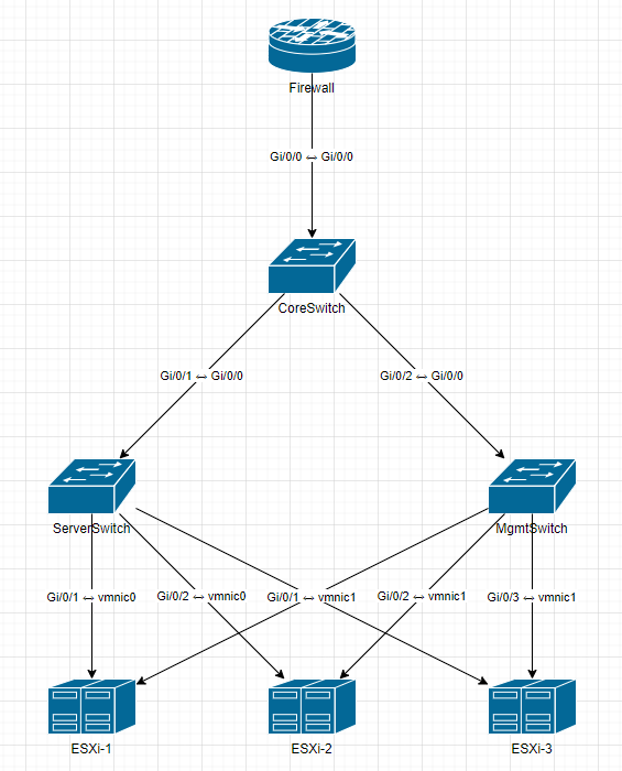
オンプレミスでファイアウォール、コアスイッチ、サーバースイッチ、管理スイッチ、ESXiサーバが接続している環境を例としています。

プログラムを実行後、XMLファイルをインポートすると、下記の様な構成図が作成されます。
新規作成手順
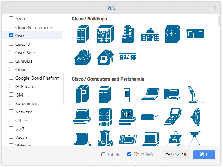
drow.ioを起動して「+その他の図形」からCiscoを追加しておきます。
下記プログラムをnetwork.pyとして保存します。ネットワークデバイス情報という箇所でデバイス情報を管理しており、接続情報という箇所でデバイス間の接続情報を管理しています。各項目にデバイス情報を追加したり、接続情報を追加することで構成図を管理することが出来ます。
import xml.etree.ElementTree as ET

# ネットワークデバイス情報
devices = {
    "Firewall": {"type": "Firewall", "shape": "mxgraph.cisco.security.router_firewall", "x": 300, "y": 100, "color": {"fill": "#036897", "stroke": "#ffffff"}},
    "CoreSwitch": {"type": "Switch", "shape": "mxgraph.cisco.switches.workgroup_switch", "x": 300, "y": 300, "color": {"fill": "#036897", "stroke": "#ffffff"}},
    "ServerSwitch": {"type": "Switch", "shape": "mxgraph.cisco.switches.workgroup_switch", "x": 100, "y": 500, "color": {"fill": "#036897", "stroke": "#ffffff"}},
    "MgmtSwitch": {"type": "Switch", "shape": "mxgraph.cisco.switches.workgroup_switch", "x": 500, "y": 500, "color": {"fill": "#036897", "stroke": "#ffffff"}},
    "ESXi-1": {"type": "Server", "shape": "mxgraph.cisco.servers.standard_host", "x": 100, "y": 700, "color": {"fill": "#036897", "stroke": "#ffffff"}},
    "ESXi-2": {"type": "Server", "shape": "mxgraph.cisco.servers.standard_host", "x": 300, "y": 700, "color": {"fill": "#036897", "stroke": "#ffffff"}},
    "ESXi-3": {"type": "Server", "shape": "mxgraph.cisco.servers.standard_host", "x": 500, "y": 700, "color": {"fill": "#036897", "stroke": "#ffffff"}},
}


# 接続情報
connections = [
    ("Firewall", "Gi/0/0", "CoreSwitch", "Gi/0/0"),
    ("CoreSwitch", "Gi/0/1", "ServerSwitch", "Gi/0/0"),
    ("CoreSwitch", "Gi/0/2", "MgmtSwitch", "Gi/0/0"),
    ("ServerSwitch", "Gi/0/1", "ESXi-1", "vmnic0"),
    ("ServerSwitch", "Gi/0/2", "ESXi-2", "vmnic0"),
    ("ServerSwitch", "Gi/0/3", "ESXi-3", "vmnic0"),
    ("MgmtSwitch", "Gi/0/1", "ESXi-1", "vmnic1"),
    ("MgmtSwitch", "Gi/0/2", "ESXi-2", "vmnic1"),
    ("MgmtSwitch", "Gi/0/3", "ESXi-3", "vmnic1"),
]

# draw.io XML の基盤作成
def create_drawio_xml():
    root = ET.Element("mxGraphModel", dx="1000", dy="800", grid="1", page="1", pageWidth="800", pageHeight="1000")
    root_node = ET.SubElement(root, "root")
    ET.SubElement(root_node, "mxCell", id="0")
    ET.SubElement(root_node, "mxCell", id="1", parent="0")
    return root, root_node

# デバイス追加
def add_device(root_node, device_id, name, shape, x, y, fill_color, stroke_color):
    cell = ET.SubElement(root_node, "mxCell", id=str(device_id), value=name,
                         style=f"shape={shape};verticalLabelPosition=bottom;verticalAlign=top;"
                               f"fillColor={fill_color};strokeColor={stroke_color};",
                         vertex="1", parent="1")
    ET.SubElement(cell, "mxGeometry", attrib={"x": str(x), "y": str(y), "width": "80", "height": "50", "as": "geometry"})
    return cell


# 接続線追加
def add_link(root_node, link_id, source_id, source_port, target_id, target_port):
    cell = ET.SubElement(root_node, "mxCell", id=str(link_id), edge="1", parent="1",
                         source=str(source_id), target=str(target_id),
                         value=f"{source_port} ↔ {target_port}")
    ET.SubElement(cell, "mxGeometry", attrib={"relative": "1", "as": "geometry"})
    return cell

# XML 作成
root, root_node = create_drawio_xml()

# デバイス追加
device_ids = {}
device_counter = 2
for name, info in devices.items():
    device_ids[name] = device_counter
    add_device(root_node, device_counter, name, info["shape"], info["x"], info["y"],info["color"]["fill"], info["color"]["stroke"])
    device_counter += 1


# 接続追加
link_counter = 100
for source, source_port, target, target_port in connections:
    add_link(root_node, link_counter, device_ids[source], source_port, device_ids[target], target_port)
    link_counter += 1

# XML 保存
tree = ET.ElementTree(root)
tree.write("network_topology.xml", encoding="utf-8", xml_declaration=True)

print("✅ draw.io 用のXMLが生成されました: network_topology.xml")
上記ファイルを実行すると、network_topology.xmlというファイルが作成されます。
python network.py
✅ draw.io 用のXMLが生成されました: network_topology.xml
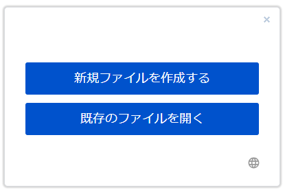
drow.ioを起動して、「既存のファイルを開く」を選択後、network_topology.xmlを指定します。
下記の様な構成図が作成されます。
更新手順
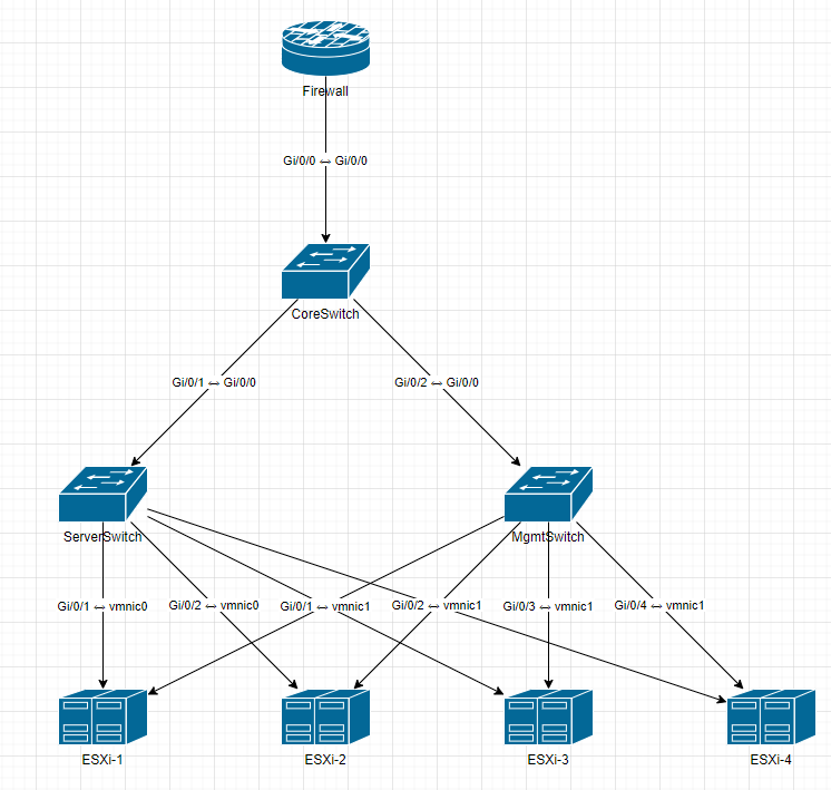
ESXi-4を1台追加してみます。
device = の箇所に下記を追加します。
"ESXi-4": {"type": "Server", "shape": "mxgraph.cisco.servers.standard_host", "x": 700, "y": 700, "color": {"fill": "#036897", "stroke": "#ffffff"}},
connections = の箇所に下記を追加します。
    ("ServerSwitch", "Gi/0/4", "ESXi-4", "vmnic0"),
    ("ServerSwitch", "Gi/0/4", "ESXi-4", "vmnic0"),
import xml.etree.ElementTree as ET

# ネットワークデバイス情報
devices = {
    "Firewall": {"type": "Firewall", "shape": "mxgraph.cisco.security.router_firewall", "x": 300, "y": 100, "color": {"fill": "#036897", "stroke": "#ffffff"}},
    "CoreSwitch": {"type": "Switch", "shape": "mxgraph.cisco.switches.workgroup_switch", "x": 300, "y": 300, "color": {"fill": "#036897", "stroke": "#ffffff"}},
    "ServerSwitch": {"type": "Switch", "shape": "mxgraph.cisco.switches.workgroup_switch", "x": 100, "y": 500, "color": {"fill": "#036897", "stroke": "#ffffff"}},
    "MgmtSwitch": {"type": "Switch", "shape": "mxgraph.cisco.switches.workgroup_switch", "x": 500, "y": 500, "color": {"fill": "#036897", "stroke": "#ffffff"}},
    "ESXi-1": {"type": "Server", "shape": "mxgraph.cisco.servers.standard_host", "x": 100, "y": 700, "color": {"fill": "#036897", "stroke": "#ffffff"}},
    "ESXi-2": {"type": "Server", "shape": "mxgraph.cisco.servers.standard_host", "x": 300, "y": 700, "color": {"fill": "#036897", "stroke": "#ffffff"}},
    "ESXi-3": {"type": "Server", "shape": "mxgraph.cisco.servers.standard_host", "x": 500, "y": 700, "color": {"fill": "#036897", "stroke": "#ffffff"}},
    "ESXi-4": {"type": "Server", "shape": "mxgraph.cisco.servers.standard_host", "x": 700, "y": 700, "color": {"fill": "#036897", "stroke": "#ffffff"}},
}


# 接続情報
connections = [
    ("Firewall", "Gi/0/0", "CoreSwitch", "Gi/0/0"),
    ("CoreSwitch", "Gi/0/1", "ServerSwitch", "Gi/0/0"),
    ("CoreSwitch", "Gi/0/2", "MgmtSwitch", "Gi/0/0"),
    ("ServerSwitch", "Gi/0/1", "ESXi-1", "vmnic0"),
    ("ServerSwitch", "Gi/0/2", "ESXi-2", "vmnic0"),
    ("ServerSwitch", "Gi/0/3", "ESXi-3", "vmnic0"),
    ("ServerSwitch", "Gi/0/4", "ESXi-4", "vmnic0"),
    ("MgmtSwitch", "Gi/0/1", "ESXi-1", "vmnic1"),
    ("MgmtSwitch", "Gi/0/2", "ESXi-2", "vmnic1"),
    ("MgmtSwitch", "Gi/0/3", "ESXi-3", "vmnic1"),
    ("MgmtSwitch", "Gi/0/4", "ESXi-4", "vmnic1")
]

# draw.io XML の基盤作成
def create_drawio_xml():
    root = ET.Element("mxGraphModel", dx="1000", dy="800", grid="1", page="1", pageWidth="800", pageHeight="1000")
    root_node = ET.SubElement(root, "root")
    ET.SubElement(root_node, "mxCell", id="0")
    ET.SubElement(root_node, "mxCell", id="1", parent="0")
    return root, root_node

# デバイス追加
def add_device(root_node, device_id, name, shape, x, y, fill_color, stroke_color):
    cell = ET.SubElement(root_node, "mxCell", id=str(device_id), value=name,
                         style=f"shape={shape};verticalLabelPosition=bottom;verticalAlign=top;"
                               f"fillColor={fill_color};strokeColor={stroke_color};",
                         vertex="1", parent="1")
    ET.SubElement(cell, "mxGeometry", attrib={"x": str(x), "y": str(y), "width": "80", "height": "50", "as": "geometry"})
    return cell


# 接続線追加
def add_link(root_node, link_id, source_id, source_port, target_id, target_port):
    cell = ET.SubElement(root_node, "mxCell", id=str(link_id), edge="1", parent="1",
                         source=str(source_id), target=str(target_id),
                         value=f"{source_port} ↔ {target_port}")
    ET.SubElement(cell, "mxGeometry", attrib={"relative": "1", "as": "geometry"})
    return cell

# XML 作成
root, root_node = create_drawio_xml()

# デバイス追加
device_ids = {}
device_counter = 2
for name, info in devices.items():
    device_ids[name] = device_counter
    add_device(root_node, device_counter, name, info["shape"], info["x"], info["y"],info["color"]["fill"], info["color"]["stroke"])
    device_counter += 1


# 接続追加
link_counter = 100
for source, source_port, target, target_port in connections:
    add_link(root_node, link_counter, device_ids[source], source_port, device_ids[target], target_port)
    link_counter += 1

# XML 保存
tree = ET.ElementTree(root)
tree.write("network_topology.xml", encoding="utf-8", xml_declaration=True)

print("✅ draw.io 用のXMLが生成されました: network_topology.xml")
上記ファイルをnetwork2.pyとして保存後、実行します。
python network2.py
✅ draw.io 用のXMLが生成されました: network_topology.xml
新規作成時の手順同様にdrow.ioを起動して、「既存のファイルを開く」を選択後、network_topology.xmlを指定します。ESXiが1台追加された構成図が作成されました。