ソフトウェアラスタライザー基本実装編 04.ポリゴン描画
前回まででポリゴンを描画するための準備は終わりましたので今回は三角形を塗りつぶしてポリゴンの描画をしていきます。
リポジトリ
今回のビルド結果は以下のような感じです。
ポリゴンがラスタライズされています。

ライトの準備
ただポリゴンを塗りつぶすだけだと画面一面真っ白になってしまってわけが分からなくなるので、今回はライティングも一緒に行います。
Renderer.h/Renderer.cppにライトを設定するためのメソッドを追加します。
void SetDirectionalLight(const Vector3& Direction);
Application.cpp側で実際にライトのパラメーターを設定しています。
_pRenderer->SetDirectionalLight(Vector3{ 1.0f, -2.0f, 5.0f });
モデルの読み込み時に法線も読み込むようにしておきます。
struct IMeshData
{
	virtual const int32 GetVertexCount() const = 0;
	virtual const int32 GetIndexCount() const = 0;

	virtual const Vector3* const GetPosition() const = 0;
	virtual const Vector3* const GetNormal() const = 0;
	virtual const uint16* const GetIndex() const = 0;
};
これでライティングを行うための準備ができました。
三角形の内外判定
10年以上前に作ったラスタライザーではスキャンライン方を用いて塗りつぶしを行いましたが、今回は外積を用いて内外判定を行って三角形を塗りつぶしていきます。
todo:図を用意する・・・
外積の箇所です。
2次元座標での外積なのでfloat値で取得できます。
fp32 Renderer::EdgeFunc(const fp32 ax, const fp32 ay, const fp32 bx, const fp32 by, const fp32 cx, const fp32 cy)
{
	return ((bx - ax) * (cy - ay)) - ((by - ay) * (cx - ax));
}
上記のメソッドを使って内外判定を行っている箇所です。
void Renderer::RasterizeTriangle(InternalVertex v0, InternalVertex v1, InternalVertex v2)
{
	// 三角形の各位置
	const auto& p0 = v0.Position;
	const auto& p1 = v1.Position;
	const auto& p2 = v2.Position;

	// 三角形の各法線
	const auto& n0 = v0.Normal;
	const auto& n1 = v1.Normal;
	const auto& n2 = v2.Normal;

	// 外積から面の向きを求めて、裏向きなら破棄する(backface-culling)
	const auto Denom = EdgeFunc(p0.x, p0.y, p1.x, p1.y, p2.x, p2.y);
	if (Denom <= 0.0f) return;

	// ポリゴンのバウンディングを求める
	auto bbMinX = p0.x, bbMinY = p0.y, bbMaxX = p0.x, bbMaxY = p0.y;
	if (bbMaxX < p1.x) bbMaxX = p1.x;
	if (bbMaxX < p2.x) bbMaxX = p2.x;
	if (bbMaxY < p1.y) bbMaxY = p1.y;
	if (bbMaxY < p2.y) bbMaxY = p2.y;
	if (bbMinX > p1.x) bbMinX = p1.x;
	if (bbMinX > p2.x) bbMinX = p2.x;
	if (bbMinY > p1.y) bbMinY = p1.y;
	if (bbMinY > p2.y) bbMinY = p2.y;

	const auto x0 = int16(bbMinX);
	const auto x1 = int16(bbMaxX);
	const auto y0 = int16(bbMinY);
	const auto y1 = int16(bbMaxY);

	auto pColorBuffer = _pColorBuffer->GetPixelPointer(x0, y0);

	// 求めたバウンディング内をforで回す
	fp32 py = fp32(y0) + 0.5f;
	for (int32 y = y0; y <= y1; ++y, py += 1.0f)
	{
		int32 x_offset = 0;
		fp32 px = fp32(x0) + 0.5f;
		for (auto x = x0; x <= x1; ++x, px += 1.0f, ++x_offset)
		{
			// 辺1-2に対して内外判定
			auto b0 = EdgeFunc(p1.x, p1.y, p2.x, p2.y, px, py);
			if (b0 < 0.0f) continue;
			// 辺2-0に対して内外判定
			auto b1 = EdgeFunc(p2.x, p2.y, p0.x, p0.y, px, py);
			if (b1 < 0.0f) continue;
			// 辺0-1に対して内外判定
			auto b2 = EdgeFunc(p0.x, p0.y, p1.x, p1.y, px, py);
			if (b2 < 0.0f) continue;

			b0 /= Denom;
			b1 /= Denom;
			b2 /= Denom;

			// 重心座標系で法線を求める
			Vector3 Normal = {
				((b0 * n0.x) + (b1 * n1.x) + (b2 * n2.x)),
				((b0 * n0.y) + (b1 * n1.y) + (b2 * n2.y)),
				((b0 * n0.z) + (b1 * n1.z) + (b2 * n2.z)),
			};

			// 適当な感じでライティングする
			Vector_Normalize(Normal, Normal);
			const auto NdotL = Vector_DotProduct(Normal, _DirectionalLight) * 0.25f + 0.75f;

			const auto Brightness = uint32(NdotL * 255.0f);

			auto& ColorBuff = pColorBuffer[x_offset];
			ColorBuff.r = Brightness;
			ColorBuff.g = Brightness;
			ColorBuff.b = Brightness;
		}

		pColorBuffer += SCREEN_WIDTH;
	}
}
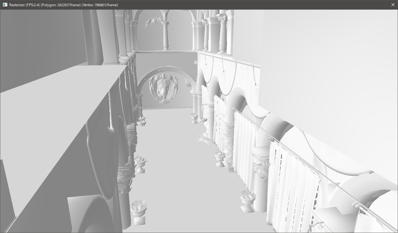
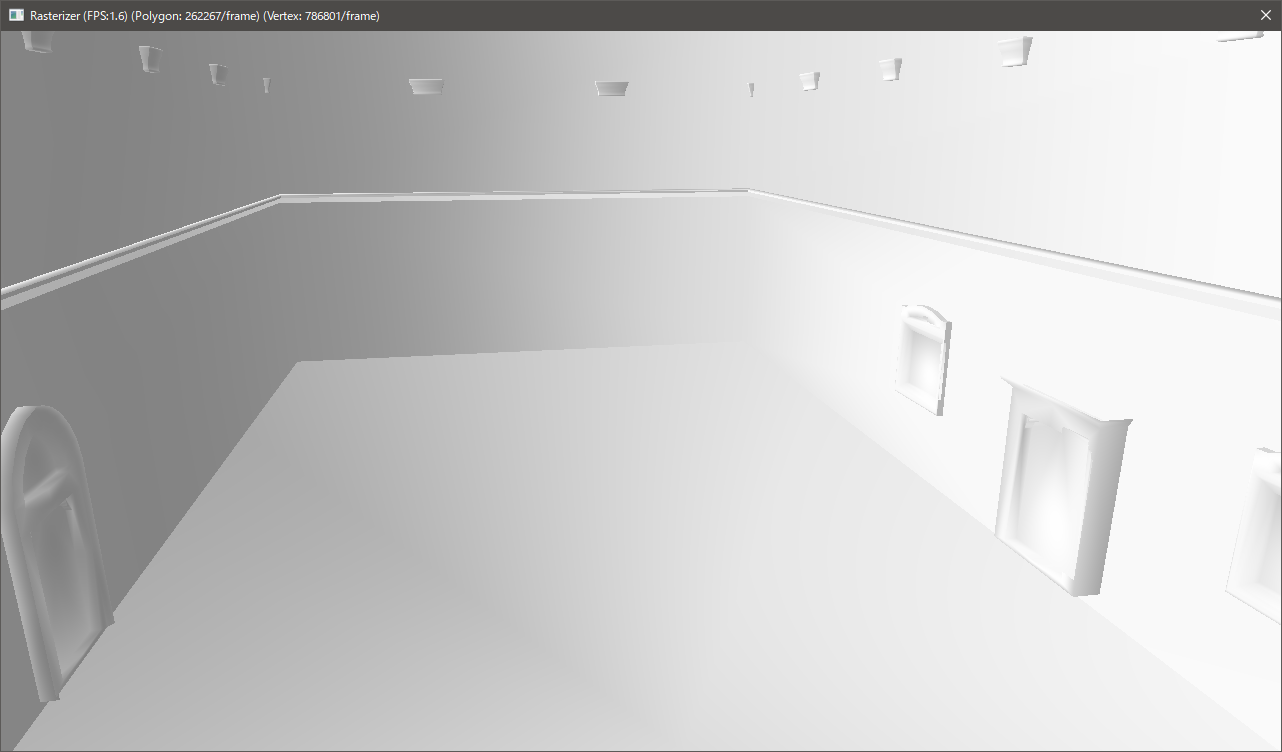
実行した結果が以下のスクショになります。

ポリゴンが塗りつぶされているのがわかります。
この状態では描画順番を制御していないため見た目がおかしな感じになっています。
今回はポリゴン単位でソートをして奥から手前に順番にポリゴンを描画するようにしてみましょう。
ポリゴンのソート
ソートをするために三角形単位でデータを保持する必要があります。
今回は以下のような構造体を用意して格納することにします。
	struct SortTriangleData
	{
		fp32 z;
		const IMeshData* pMesh;
		Vector4 Position[3];
		Vector3 Normal[3];
	};
	static std::vector<SortTriangleData> SortTriangleDatas;
zにはポリゴンを構成する3頂点の中心のzを入れています。
これを元にソートをしてポリゴンの描画を行ったものが冒頭のスクリーンショットになります。
	// ここでソートを行う
	std::sort(
		SortTriangleDatas.begin(),
		SortTriangleDatas.end(),
		[](SortTriangleData& l, SortTriangleData& r) { return l.z > r.z; });

	// ソート結果に合わせて描画
	for (auto&& Mesh : SortTriangleDatas)
	{
		static const uint16_t IndexTbl[] = { 0, 1, 2 };
		RenderTriangle(
			Mesh.pMesh,
			Mesh.Position,
			Mesh.Normal,
			3,
			IndexTbl,
			3);
	}
最後に
今回はポリゴンの描画を行いました。
シンプルにポリゴン単位で奥からソートをしているだけなのでサイズの大きいポリゴンやポリゴン同士の重なりで見た目がおかしくなっています。
全体的にかなり処理が重くなりました。塗りつぶすピクセル数が激増したのもありますしポリゴン単位でソートをしているというのもあります。
ソートのコストを減らすために昔のハードでは深度に応じたテーブルを用意してテーブルに挿入する形をとっていた時代もありましたが、メモリが安価になった今では深度バッファを使う方が一般的なので次回は深度バッファを導入してみようと思います。