シスコ DevNet では、ネットワークを簡単に描画できる NeXt UI が公開されています。ここでは、実際にブラウザで描画するまでの簡単なメモをまとめます。
ダウンロード
まずは必要なパッケージを以下からダウンロードします。
https://developer.cisco.com/site/neXt/
サイズは 1.2M とかなり小さいです。
ダウンロード後、解凍すると dest というフォルダが現れます。
~/Downloads$ ls
NeXt_trial.zip
~/Downloads$ unzip NeXt_trial.zip
(略)
~/Downloads$ ls
dest  NeXt_trial.zip
実際に描画させてみよう
NeXt UI を使って描画するのはとても簡単です。
ここからは、下記 Learn セッションにある Create a Topology を参考にしています。
まず適当なフォルダを作り、上記で展開した dest をコピーします。
~$ mkdir nextui-test
~$ cd nextui-test/
~/nextui-test$ mkdir next
~/nextui-test$ mv ~/Downloads/dest next/
~/nextui-test$ ls
next
~/nextui-test$
次に、同じフォルダに、下記のような index.html を作ります。
~/nextui-test$ cat index.html
<html>
<head>
        <link rel="stylesheet" href="next/dest/css/next.css">
        <script src="next/dest/js/next.js"></script>
        <script src="Data.js"></script>
        <script src="Shell.js"></script>
</head>
<body>
Cisco NeXt UI
</body>
</html>

~/nextui-test$
同じフォルダに、Hello.js と Shell.js を下記のように作ります(上記 DevNet からのコピペです)。
~/nextui-test$ cat Data.js
var topologyData = {
    nodes: [
        {"id": 0, "x": 410, "y": 100, "name": "12K-1"},
        {"id": 1, "x": 410, "y": 280, "name": "12K-2"},
        {"id": 2, "x": 660, "y": 280, "name": "Of-9k-03"},
        {"id": 3, "x": 660, "y": 100, "name": "Of-9k-02"},
        {"id": 4, "x": 180, "y": 190, "name": "Of-9k-01"}
    ],
    links: [
        {"source": 0, "target": 1},
        {"source": 1, "target": 2},
        {"source": 1, "target": 3},
        {"source": 4, "target": 1},
        {"source": 2, "target": 3},
        {"source": 2, "target": 0},
        {"source": 3, "target": 0},
        {"source": 3, "target": 0},
        {"source": 3, "target": 0},
        {"source": 0, "target": 4},
        {"source": 0, "target": 4},
        {"source": 0, "target": 3}
    ]
};
~/nextui-test$
~/nextui-test$ cat Shell.js
(function (nx) {
    /**
     * define application
     */
    var Shell = nx.define(nx.ui.Application, {
        methods: {
            start: function () {
                //your application main entry

                // initialize a topology
                var topo = new nx.graphic.Topology({
                    // set the topology view's with and height
                    width: 580,
                    height: 580,
                    // node config
                    nodeConfig: {
                        // label display name from of node's model, could change to 'model.id' to show id
                        label: 'model.name'
                    },
                    // link config
                    linkConfig: {
                        // multiple link type is curve, could change to 'parallel' to use parallel link
                        linkType: 'curve'
                    },
                    // show node's icon, could change to false to show dot
                    showIcon: true
                });

                //set data to topology
                topo.data(topologyData);
                //attach topology to document
                topo.attach(this);
            }
        }
    });

    /**
     * create application instance
     */
    var shell = new Shell();

    /**
     * invoke start method
     */
    shell.start();
})(nx);
~/nextui-test$
必要な作業は以上で完了です。
最終的なファイル構造は下記のようになります。
nextui-test/
├── Data.js
├── index.html
├── next
│   └── dest
└── Shell.js
ブラウザで見てみよう
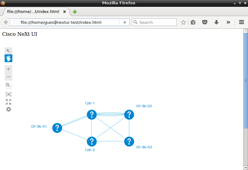
先ほどの index.html をブラウザで開くと、下記のようにネットワークトポロジが描画されているのが確認できます。
非常に簡単ですね!
