やった事
OV7670の初期化パメーターに追加を行い、VAGとQQVGAの撮影を可能とした。
これに合わせて表示ソフトも変更を加えた。
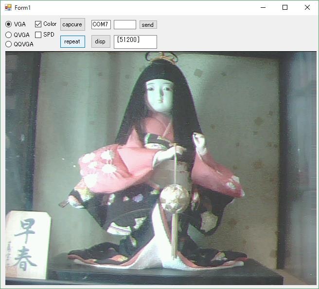
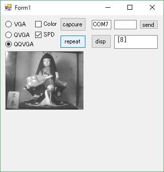
撮影例
(1)VGA(640x480)カラー
(2)QQVGA(160x120)モノクロ
撮影速度
(1)VGA
通常モード モノクロ 4.1秒、カラー 7.9秒
(2)QVGA
通常モード モノクロ 2.1秒 カラー 4.1秒
高速モード 1.2秒 2.1秒
(3)QQVGA
通常モード モノクロ 1.2秒 カラー 2.1秒
高速モード 0.4秒 カラー 0.6秒
評価
Arduinoでここまで出来る事は技術的には面白いが、VGAカラーでは8秒要しており、用途として微速度撮影ぐらいしか思いつかない。
QQVGA高速モードモノクロでは0.4秒(2.5fps)で撮影できており、簡易な画像センサーとして使えるかも知れない。
いずれにせよ、高速(高価)なチップを使えば出来るのは当たり前であり、Arduinoの範疇で何か出来ないか考えたい。
ソフト
「uno_ov7670.ino」ver1.2
表示ソフトは [その2 画像の表示]
// Source code for application to transmit image from ov7670 to PC via USB
// By Siarhei Charkes in 2015
// http://privateblog.info

# include <stdint.h>
# include <avr/io.h>
# include <util/twi.h>
# include <util/delay.h>
# include <avr/pgmspace.h>

# define camAddr_WR  0x42
# define camAddr_RD  0x43
# define REG_COM7  0x12
# define REG_COM10 0x15  // Control 10 //
# define REG_COM14 0x3e  // Control 14 //
# define REG_COM15 0x40  // Control 15 //

uint8_t cammd0=0, cammd1=0, cammd2=0;
struct regval_list{ uint8_t reg_num; uint16_t value; };
const struct regval_list ov7670_default_regs[] PROGMEM = {
  {0x3a,0x04},{0x40,0xd0},{0x12,0x14},{0x32,0x80},{0x17,0x16},{0x18,0x04},{0x19,0x02},{0x1a,0x7b},
  {0x03,0x06},{0x0c,0x00},{0x3e,0x00},{0x70,0x00},{0x71,0x00},{0x72,0x11},{0x73,0x00},{0xa2,0x02},
  {0x11,0x81},{0x7a,0x20},{0x7b,0x1c},{0x7c,0x28},{0x7d,0x3c},{0x7e,0x55},{0x7f,0x68},{0x80,0x76},
  {0x81,0x80},{0x82,0x88},{0x83,0x8f},{0x84,0x96},{0x85,0xa3},{0x86,0xaf},{0x87,0xc4},{0x88,0xd7},
  {0x89,0xe8},{0x13,0xe0},{0x00,0x00},{0x10,0x00},{0x0d,0x00},{0x14,0x28},{0xa5,0x05},{0xab,0x07},
  {0x24,0x75},{0x25,0x63},{0x26,0xA5},{0x9f,0x78},{0xa0,0x68},{0xa1,0x03},{0xa6,0xdf},{0xa7,0xdf},
  {0xa8,0xf0},{0xa9,0x90},{0xaa,0x94},{0x13,0xe5},{0x0e,0x61},{0x0f,0x4b},{0x16,0x02},{0x1e,0x37}, //{0x1e,0x17}
  {0x21,0x02},{0x22,0x91},{0x29,0x07},{0x33,0x0b},{0x35,0x0b},{0x37,0x1d},{0x38,0x71},{0x39,0x2a},
  {0x3c,0x78},{0x4d,0x40},{0x4e,0x20},{0x69,0x00},{0x6b,0x00},{0x74,0x19},{0x8d,0x4f},{0x8e,0x00},
  {0x8f,0x00},{0x90,0x00},{0x91,0x00},{0x92,0x00},{0x96,0x00},{0x9a,0x80},{0xb0,0x84},{0xb1,0x0c},
  {0xb2,0x0e},{0xb3,0x82},{0xb8,0x0a},{0x43,0x14},{0x44,0xf0},{0x45,0x34},{0x46,0x58},{0x47,0x28},
  {0x48,0x3a},{0x59,0x88},{0x5a,0x88},{0x5b,0x44},{0x5c,0x67},{0x5d,0x49},{0x5e,0x0e},{0x64,0x04},
  {0x65,0x20},{0x66,0x05},{0x94,0x04},{0x95,0x08},{0x6c,0x0a},{0x6d,0x55},{0x6e,0x11},{0x6f,0x9f},
  {0x6a,0x40},{0x01,0x40},{0x02,0x40},{0x13,0xe7},{0x15,0x02},{0x4f,0x80},{0x50,0x80},{0x51,0x00},
  {0x52,0x22},{0x53,0x5e},{0x54,0x80},{0x58,0x9e},{0x41,0x08},{0x3f,0x00},{0x75,0x05},{0x76,0xe1},
  {0x4c,0x00},{0x77,0x01},{0x3d,0xc2},{0x4b,0x09},{0xc9,0x60},{0x41,0x38},{0x56,0x40},{0x34,0x11},
  {0x3b,0x02},{0xa4,0x89},{0x96,0x00},{0x97,0x30},{0x98,0x20},{0x99,0x30},{0x9a,0x84},{0x9b,0x29},
  {0x9c,0x03},{0x9d,0x4c},{0x9e,0x3f},{0x78,0x04},{0x79,0x01},{0xc8,0xf0},{0x79,0x0f},{0xc8,0x00},
  {0x79,0x10},{0xc8,0x7e},{0x79,0x0a},{0xc8,0x80},{0x79,0x0b},{0xc8,0x01},{0x79,0x0c},{0xc8,0x0f},
  {0x79,0x0d},{0xc8,0x20},{0x79,0x09},{0xc8,0x80},{0x79,0x02},{0xc8,0xc0},{0x79,0x03},{0xc8,0x40},
  {0x79,0x05},{0xc8,0x30},{0x79,0x26},{0x09,0x03},{0x3b,0x42},{0xff,0xff},
};

void error_led(void){
  DDRB |= 32;//make sure led is output
  while (1){//wait for reset
    PORTB ^= 32;// toggle led
    _delay_ms(100);
  }
}

void twiStart(void){
  TWCR = _BV(TWINT) | _BV(TWSTA) | _BV(TWEN);//send start
  while (!(TWCR & (1 << TWINT)));//wait for start to be transmitted
  if ((TWSR & 0xF8) != TW_START)
    error_led();
}

void twiWriteByte(uint8_t DATA, uint8_t type){
  TWDR = DATA;
  TWCR = _BV(TWINT) | _BV(TWEN);
  while (!(TWCR & (1 << TWINT))) {}
  if ((TWSR & 0xF8) != type)
    error_led();
}

void twiAddr(uint8_t addr, uint8_t typeTWI){
  TWDR = addr;//send address
  TWCR = _BV(TWINT) | _BV(TWEN);    /* clear interrupt to start transmission */
  while ((TWCR & _BV(TWINT)) == 0); /* wait for transmission */
  if ((TWSR & 0xF8) != typeTWI)
    error_led();
}

void wrReg(uint8_t reg, uint8_t dat){
  //send start condition
  twiStart();
  twiAddr(camAddr_WR, TW_MT_SLA_ACK);
  twiWriteByte(reg, TW_MT_DATA_ACK);
  twiWriteByte(dat, TW_MT_DATA_ACK);
  TWCR = (1 << TWINT) | (1 << TWEN) | (1 << TWSTO);//send stop
  _delay_ms(1);
}

static uint8_t twiRd(uint8_t nack){
  if (nack){
    TWCR = _BV(TWINT) | _BV(TWEN);
    while ((TWCR & _BV(TWINT)) == 0); /* wait for transmission */
    if ((TWSR & 0xF8) != TW_MR_DATA_NACK)
      error_led();
    return TWDR;
  }
  else{
    TWCR = _BV(TWINT) | _BV(TWEN) | _BV(TWEA);
    while ((TWCR & _BV(TWINT)) == 0); /* wait for transmission */
    if ((TWSR & 0xF8) != TW_MR_DATA_ACK)
      error_led();
    return TWDR;
  }
}

uint8_t rdReg(uint8_t reg){
  uint8_t dat;
  twiStart();
  twiAddr(camAddr_WR, TW_MT_SLA_ACK);
  twiWriteByte(reg, TW_MT_DATA_ACK);
  TWCR = (1 << TWINT) | (1 << TWEN) | (1 << TWSTO);//send stop
  _delay_ms(1);
  twiStart();
  twiAddr(camAddr_RD, TW_MR_SLA_ACK);
  dat = twiRd(1);
  TWCR = (1 << TWINT) | (1 << TWEN) | (1 << TWSTO);//send stop
  _delay_ms(1);
  return dat;
}

void wrSensorRegs8_8(const struct regval_list reglist[]){
  uint8_t reg_addr, reg_val;
  const struct regval_list *next = reglist;
  while ((reg_addr != 0xff) | (reg_val != 0xff)){
    reg_addr = pgm_read_byte(&next->reg_num);
    reg_val = pgm_read_byte(&next->value);
    wrReg(reg_addr, reg_val);
    next++;
  }
}

void arduinoUnoInut(void) {
  //cli();//disable interrupts

  /* Setup the 8mhz PWM clock  * This will be on pin 11*/
  DDRB |= (1 << 3);//pin 11
  ASSR &= ~(_BV(EXCLK) | _BV(AS2));
  TCCR2A = (1 << COM2A0) | (1 << WGM21) | (1 << WGM20);
  TCCR2B = (1 << WGM22) | (1 << CS20);
  OCR2A = 0;//(F_CPU)/(2*(X+1))
  DDRC &= ~15;//low d0-d3 camera
  DDRD &= ~252;//d7-d4 and interrupt pins

  //set up twi for 100khz
  TWSR &= ~3;//disable prescaler for TWI
  TWBR = 72;//set to 100khz

  //enable serial
  UBRR0H  = 0;
  UBRR0L  = 1; // 0 = 2M baud rate. 1 = 1M baud. 3 = 0.5M. 7 = 250k 207 is 9600 baud rate.
  UCSR0A |= 2;//double speed aysnc
  UCSR0B  = (1 << RXEN0) | (1 << TXEN0);//Enable receiver and transmitter
  UCSR0C  = 6;//async 1 stop bit 8bit char no parity bits
}

void camInit(void){
  wrReg(0x12, 0x80); delay(100);
  wrSensorRegs8_8(ov7670_default_regs);
  wrReg(REG_COM10, 32);//PCLK does not toggle on HBLANK.
  wrReg(0x13, 0x8f); // Set ACE
}

void cammode_select(){
  uint8_t clkspm,clkspc,com7s;
  if(cammd2==2){ // QQVGA
      com7s = 0x00;
      wrReg(0x70, 0x3a); wrReg(0x71, 0x35); wrReg(0x72, 0x22); wrReg(0x73, 0xf2);
      wrReg(0x0c, 0x04); wrReg(0x3e, 0x1a); wrReg(0xa2, 0x02);
  } else {
    if(cammd2==1){ // VGA
      com7s = 0x00;
      wrReg(0x70, 0x3a); wrReg(0x71, 0x35); wrReg(0x72, 0x11); wrReg(0x73, 0xf0);
      wrReg(0x0c, 0x00);  wrReg(0x3e, 0x00); wrReg(0xa2, 0x02);
    } else { // QVGA
      com7s = 0x10;
      wrReg(0x70, 0x3a); wrReg(0x71, 0x35); wrReg(0x72, 0x11); wrReg(0x73, 0xf1);
      wrReg(0x0c, 0x04);  wrReg(0x3e, 0x19); wrReg(0xa2, 0x02);
    }
  }

  if(cammd2==2)
    if(cammd1) { clkspm = 1; clkspc =  2;}
    else       { clkspm = 5; clkspc = 10;}
  else {
    if(cammd1) { clkspm = 5; clkspc = 10;}// Speedup
    else       { clkspm = 10; clkspc = 20;}// Normal
    if(cammd2 & 1) { clkspm = clkspm * 2; clkspc = clkspc * 2;} // if VGA
  }

  if(cammd0){ // Color
    com7s = com7s + 4; // RGB565
    wrReg(REG_COM15, 0xd0);
    wrReg(0x11, clkspc); // Coloe Mode & Slow Speed
  } else { // Mono
    com7s = com7s + 0; // YUYV
    wrReg(REG_COM15, 0xc0);
    wrReg(0x11, clkspm); //Earlier it had the value: wrReg(0x11, 12); New version works better for me :) !!!!
  }
  wrReg(REG_COM7 , com7s);
  //wrReg(0x71, 0xB5); // color bar
}

uint8_t imgbf[320];
static void captureImg( uint16_t wg, uint16_t hg){
  uint16_t y, x;
  uint8_t rm0,rm1,*imgwp,*imgrp;
  uint8_t s0s,s0b,s1s,s1b,s2s,s2b,s3s,s3b,qqvm;
  while (!(PIND & 8)); while ((PIND & 8)); // VSYNC Falling edge

  if(cammd2==2 && cammd1==1){ // QQVGA + SPD
    if(cammd0){ // Color
      s0b = 0; s1b = 1; s2b = 1;
      s0s = 1; s1s = 0; s2s = 0;
      qqvm = 0;
    } else{ // mono
      s0b = 1; s1b = 0; s2b = 1;
      s0s = 0; s1s = 0; s2s = 0;
      qqvm = 1;
    }
  } else {
    qqvm = 0;
    s0b = 0; s0s = 1;
    if(cammd0){
      if(cammd1) {s1b = 1; s1s = 0; }
      else       {s1b = 0; s1s = 1; }
    } else       {s1b = 0; s1s = 0; }
    if(cammd0 || !cammd1) {s2s = 1; s2b = 0;}
    else                  {s2s = 0; s2b = 1;}
  }

  UDR0 = 0xff; // Start Mark
  cli();
  y = hg;
  do{
    x = wg / 2;
    imgwp = &imgbf[0]; imgrp = &imgbf[0];
    do{
      while (!(PIND & 4)); while ((PIND & 4)); // PCLK Falling edge
        if(qqvm) {
          if((x & 1)==0) UDR0 = (PINC & 15) | (PIND & 240);
          else           *imgwp++ = (PINC & 15) | (PIND & 240);
        } else {
          if(s0s) UDR0 = (PINC & 15) | (PIND & 240);
          if(s0b) *imgwp++ = (PINC & 15) | (PIND & 240);
        }
      while (!(PIND & 4)); while ((PIND & 4)); // Falling edge
        if(s1s) UDR0 = (PINC & 15) | (PIND & 240);
        if(s1b) *imgwp++ = (PINC & 15) | (PIND & 240);
      while (!(PIND & 4)); while ((PIND & 4)); // Falling edge
        if(s2s) UDR0 = (PINC & 15) | (PIND & 240);
        if(s2b) *imgwp++ = (PINC & 15) | (PIND & 240);
      while (!(PIND & 4)); while ((PIND & 4)); // Falling edge
        if(s1s) UDR0 = (PINC & 15) | (PIND & 240);
        if(s1b) *imgwp++ = (PINC & 15) | (PIND & 240);
    yield();
    } while (--x);
    while(imgrp!=imgwp) {
      while (!(UCSR0A & (1 << UDRE0)));//wait for byte to transmit
      UDR0 = *imgrp++;
    yield();
    }
  } while (--y);

  for( x=0; x<8; x++){ // End Mark
    while (!(UCSR0A & (1 << UDRE0)));//wait for byte to transmit
      UDR0 = 0;
  }
  sei();
  //_delay_ms(100);
}

void wrOV7670Reg(unsigned char adr, unsigned char  dat){
  wrReg( adr, dat);
}

void setup(){
  arduinoUnoInut();
  camInit();
  cammode_select();
}

int s22hex(char * ha){
  int rc = 0,hi;
  for(int i=0; i<2; i++){
    char ch = *ha++;
    if(ch>'9') hi = (ch & 0xdf)-0x37; else hi = ch-0x30;
    rc = rc*16+hi;
  }
  return rc;
}
int rct = 0,repf = 0;
char rbf[16];
byte inChar = 0;
char * rbfp;
void docmd(){
  inChar = ' ';
  if(UCSR0A & (1<<RXC0)){
    byte kd = UDR0;
    if(kd>=0x20) { rbf[rct++] = kd; return;
    } else {
      if(kd==0x08 && rct!=0) { rct--; return; }
      else{ rbf[rct] = 0; inChar = rbf[0]; rbfp = &rbf[2]; rct = 0;}
    }
  } else if(repf==1) inChar = 'c';

  if (inChar == 'c') {
    if(rbf[1]==0){
      if(cammd2==2)   captureImg( 160, 120); // QQVGA
      else
        if(cammd2==1) captureImg( 640, 480); // VGA
        else          captureImg( 320, 240); // QVGA
    } else {
      //camcolor = rbf[1];
      cammd0 = rbf[1] & 1;
      cammd1 = (rbf[1]  >> 1) & 1;
      cammd2 = (rbf[1]  >> 2) & 3;
      cammode_select();
    }
  }
  if (inChar == 'r') repf = 1-repf;
  if (inChar == 's') { // Setup ov7670 Regs
    byte adr = s22hex(&rbf[1]);
    byte dat = s22hex(&rbf[3]);
    if(adr==0xff) setup();
    else wrReg( adr, dat);
  }
}
void loop(){
  docmd();
}
その他
上記記載のハード、ソフトは無保証であり、各自の責任においてご利用願います。