概要
M5stack basic (esp32)
https://www.switch-science.com/catalog/7362/
M5Stack用Port A I2C拡張ハブユニット(PCA9548AP)
https://www.switch-science.com/catalog/7588/
M5Stack用ADCユニット [U013]
https://www.switch-science.com/catalog/5221/
をarduino IDEで使用するやり方の備忘録。
自分がやりたかったのは、
m5stackで 0-10vの電圧を2系統測りたかった。
M5Stack用電圧計ユニット
(https://www.switch-science.com/catalog/6740/)
がとても高かったので、ADCでいいやと思って使った結果...
RAWデータが謎の数値だった。
まあ使えなくもないので、そのまま使用。
悩み
m5stack + unitを使えばハンダ付けも少なく、手軽(?)に使えて便利。
i2c通信のセンサーを使うのは何回もやったことはあるが
理解してやってるわけではない、
同じセンサー(i2cアドレスが同じ)でポートが一つしか使わないなら
hubを使えばいけると思って購入。
しかしあまり情報がなかった(公式でも不親切な説明)で、
なんとかできましたが自分のための備忘録+誰かの役に立てばと思いまとめました。
portA hubの仕組み
仕組みって書いたが、自分がどんな仕組みでできるかがパッとみわからなかったので、軽くまとめます。(arduinoの場合です)
*コードは結構飛ばしたり、ライブラリーの中身までは触ってないのです
普通のi2cセンサーの場合
(M5_ADS1100というライブラリのexample参照)
i2cアドレスはadcunitの例です(0x48)
0番と1番に同じアドレスのユニットを繋げた想定(0x48)
wire.begin();   //i2c通信宣言

int8_t address = 0x48;
Wire.beginTransmission(0x48); //これで通信確認
byte error = Wire.endTransmission();

if (error == 0)  // デバイスつながったら
    {
     int16_t result;
     result = ads.Measure_Differential();
    //中はreadRegister(adress)でデーター読む感じになってた

    }

else   //エラー
    {

    }
みたいな感じでアドレス指定して、通信するだけでした。
同じのi2cセンサー複数、hub使用の場合
m5stackのスケッチ例の中で
unit - PaHUB_TCA9548Aを参照
wire.begin(); // i2c通信宣言

tca9548a.address(0x70); //ハブのアドレス(0x70)に接続
tca9548a.selectChannel(0); //0番のチャンネルを選択

//exampleはfor文でやってる
//そこからはセンサーのアドレスに通信かける

Wire.beginTransmission(0x48); //これで通信確認
byte error = Wire.endTransmission();

if (error == 0)  // デバイスつながったら
    {
     int16_t result;
     result = ads.Measure_Differential();
    //中はreadRegister(adress)でデーター読む感じになってた

    }

else   //エラー
    {

    }

tca9548a.selectChannel(1); //1番のチャンネルを選択

Wire.beginTransmission(0x48); //これで通信確認
byte error = Wire.endTransmission();

if (error == 0)  // デバイスつながったら
    {
     int16_t result;
     result = ads.Measure_Differential();
    //中はreadRegister(adress)でデーター読む感じになってた

    }

else   //エラー
    {

    }
のような感じで、アドレスはそのままで、
ただ最初のPaHUBのライブラリーを宣言して(アドレスはhubの 0x70)
そこからは
tca9548a.selectChannel(channel);
を使ってチャンネルを変えて、センサーのアドレス(adcは 0x48)で通信するだけでした。
サンプル
PaHUB_TCA9548のサンプル
を参考にして作った、自分が使ったテストアプリのサンプルをあげときます。
なにか役に立てたらお使いください。
使用するライブラリー
ClosedCube_TCA9548A (PaHUB_TCA9548サンプルの中に入ってます)
M5_ADS1100
#include <Wire.h>
#include <M5Stack.h>
#include "M5_ADS1100.h"
#include "ClosedCube_TCA9548A.h"

#define PaHub_I2C_ADDRESS 0x70

#define FRONT 2

#define X_LOCAL 100
#define Y_LOCAL 35
#define X_OFFSET 160
#define Y_OFFSET 34

ADS1100 ads;
ClosedCube::Wired::TCA9548A tca9548a;

int rawData[6];

void setup(void) {
    M5.begin();
    M5.Power.begin();

   Wire.begin();
   tca9548a.address(PaHub_I2C_ADDRESS);

    ads.getAddr_ADS1100(ADS1100_DEFAULT_ADDRESS);  // 0x48
    ads.setGain(GAIN_ONE);  // 1x gain(default)
    ads.setMode(MODE_CONTIN);  // Continuous conversion mode (default)
    ads.setRate(RATE_8);  // 8SPS (default)
    ads.setOSMode(OSMODE_SINGLE);
   // ads.begin();  //wire.begin()がかぶるのでコメントアウト


  tca9548a.address(PaHub_I2C_ADDRESS);

  M5.Lcd.fillScreen(TFT_BLACK);
  M5.Lcd.setTextFont(4);
  M5.Lcd.setCursor(70, 0, 4);
  M5.Lcd.setTextColor(YELLOW,TFT_BLACK);
  M5.Lcd.println(("PaHUB ADCUNIT"));
  M5.Lcd.setTextColor(TFT_WHITE,TFT_BLACK);

}

void loop(void) {
    for( uint8_t channel=0; channel<TCA9548A_MAX_CHANNELS; channel++ ) {

    M5.Lcd.setCursor(X_LOCAL, Y_LOCAL + Y_OFFSET*channel , FRONT);
    M5.Lcd.printf("                                                                ");
    M5.Lcd.setCursor(X_LOCAL, Y_LOCAL + Y_OFFSET*channel , FRONT);
    M5.Lcd.printf("CH%d : ",channel);

    tca9548a.selectChannel(channel);
    byte error;
    int8_t address;
    address = ads.ads_i2cAddress;
    Wire.beginTransmission(address);
    error = Wire.endTransmission();
    if (error == 0)
    {
        int16_t result;
        result = ads.Measure_Differential();
        rawData[channel] = result * 0.515; // 0.5だと数値がおかしい
        M5.Lcd.printf("%d  ", rawData[channel]);


    } else {
      M5.Lcd.printf("noSensor");

    }


    delay(100);
    }
}
結果
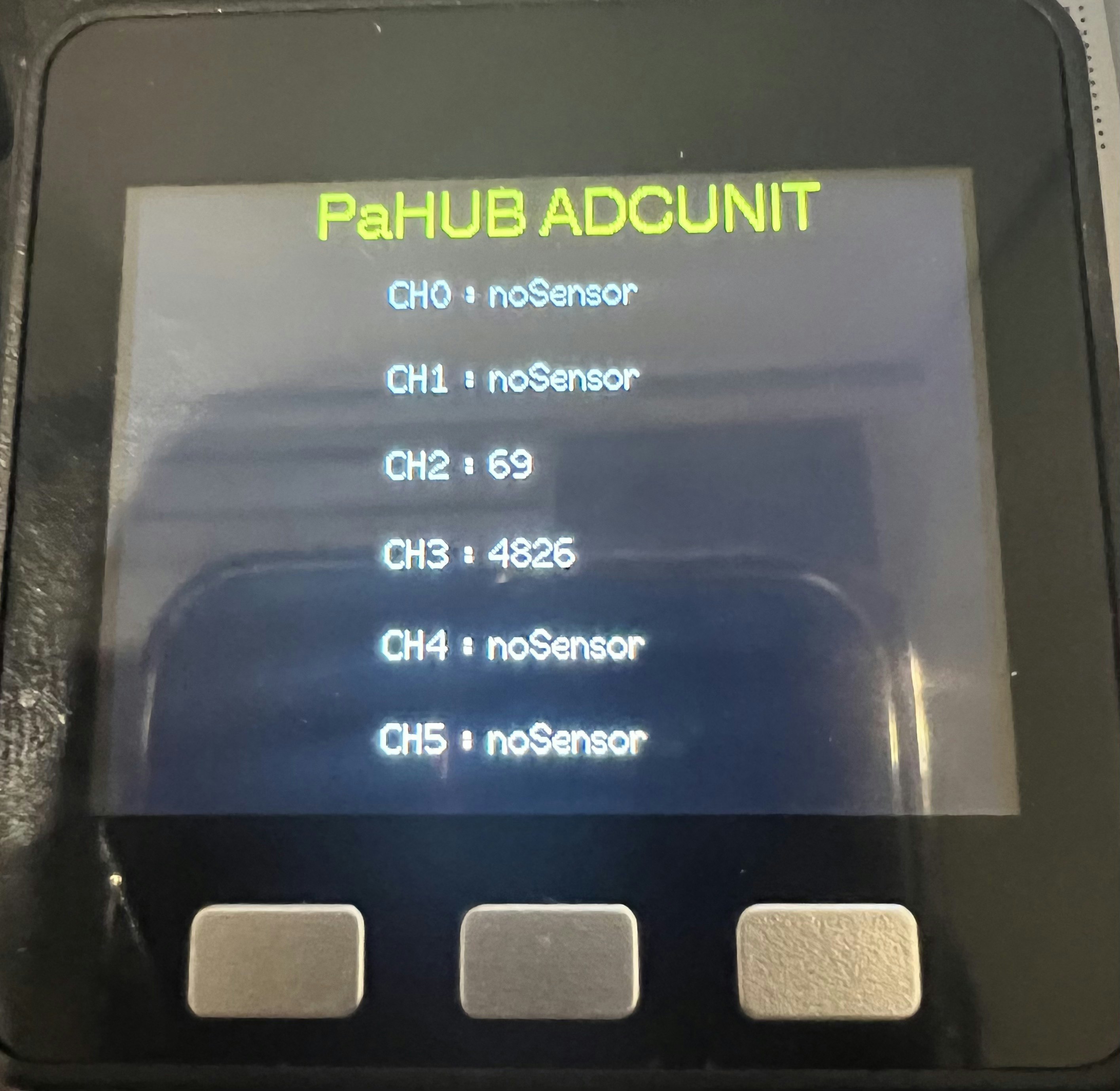
2、3番にadcunitを繋げました。
謎なのは
result * 0.515; // 0.5だと数値がおかしい
ここで、センサーの結果だと電圧の約2倍くらいの数値でした。
上記の画像で
ch2はセンサー接続のみで、なんにも繋げてない状態
ch3はm5stackの[5v]を測ってみました。
デジタルテスターだと4.84vで計測
0.515をかけることで、 4820 - 4850くらいの数値が取れました。
これは環境とかの影響があるかもしれないので、
みなさまもやってみて変えてください。
追記
@tekura555様のコメントで以下の情報がありました。
電圧違いが問題のようです。
情報ありがとうございました!
@tekura555
2022-12-11 21:30
同じ内容を疑問に思っていてM5Stackに問い合わせしていました。
回答としてはPahab挟んでADC使う場合と本体に直接ADC繋ぐ場合ではベース電圧が違うようで、これによりPahab挟んだ場合は正確な値がでないようです。
Pahabのプルアップ抵抗を取り去れば、正常な値になるとのこと。
私は基板いじる勇気が出なかったので、Pahabで使用されているのと同じICを搭載したhab基板でベース電圧が同じものを使用して解決しました。
Grove 8チャンネルI2Cマルチプレクサ/I2Cハブ(TCA9548A)
