PIC16F1827 シリアル通信
前回は、書き込み回路とリセット回路をブレッドボード上で配線しました。 今回は、パソコンとシリアル通信できるように、シリアル通信、送受信のための配線を追加しました。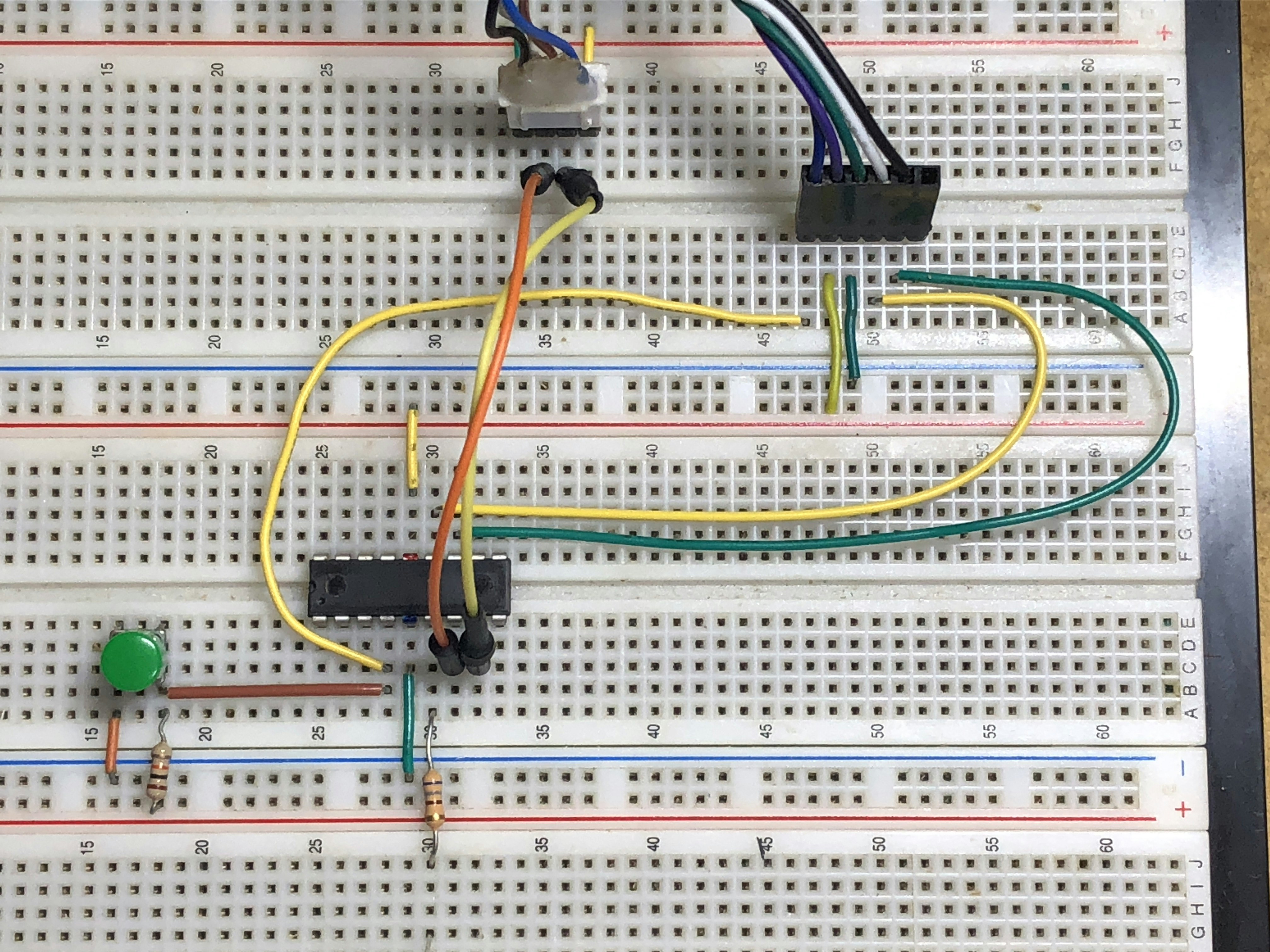
追記:25.10.13
XC8コンパイラのバージョンによっては、putch,getch関数の記述が変わります。
この記事は最初、v2.36で、記述しました。v3.00になるとエラーが出ます。
以下のように変更します。
Peripheral.h (XC8 v3.00)
プロトタイプ宣言をコメントアウト。
//extern void putch(uint8_t byte);
//extern uint8_t getch(void);
プロトタイプ宣言はあらかじめ、C99 stdio.h に記述されているので、
その宣言に沿った関数の引数に変更します。
Peripheral.c (XC8 v3.00)
void putch(char byte)//引数uint8_tをcharに変更。
{
    while(!PIR1bits.TXIF)continue;
    TXREG=byte;
}

int getch(void)//戻り値uint8_tをintに変更。
{
    while(!PIR1bits.RCIF){};
    return RCREG;
}
これで、XC8コンパイラのv3.00でも、コンパイルが通るようになります。
25.10.13 修正:パワーオンリセット時に、シリアル通信で、パソコンに'?'マークが送信されてしまうバグの修正。
main.c
<略>
    Oscillator_Init();
    Port_Init();
    __delay_ms(100);//25.10.13 ?マークが出力するバグをださないために追記。
    //Peripheral初期化
    Timer0_INIT();
IOポートの初期化処理後にディレイタイマーを設定すると、'?'マークの出力がなくなった。
すべてのPICマイコンのIO初期化後に、100msぐらいの遅延が必要なのかもしれないので、今後注意してみる。
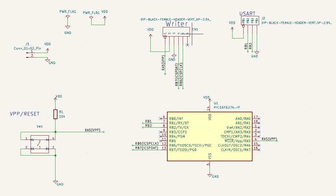
回路図
USBシリアル変換器 MCP2221
パソコンと通信するために、USBシリアル変換器MCP2221を使用しました。
PICマイコンのTX,RX端子とクロスさせて接続します。
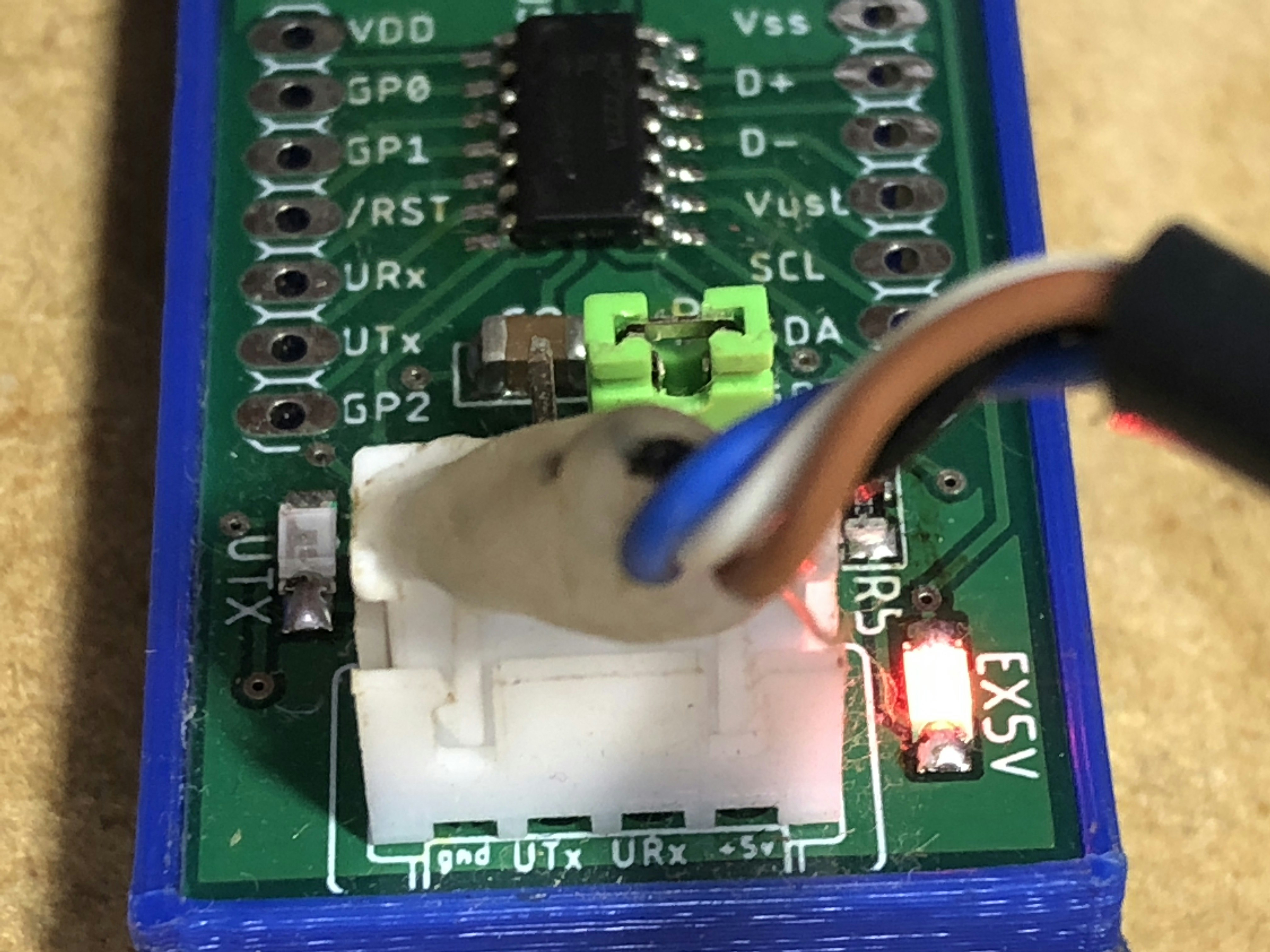
コネクタ端子は、
左から、GND、UTx、URx、VDD(5V)になっています。UTx,URxは、MCP2221の端子名。
PIC側のRXとUSBシリアル変換器のUTXを、
PIC側のTXとUSBシリアル変換器のURXを接続します。
※基板は自作の回路図から発注したものなので、市販品ではありません。
シリアル通信コード
Peripheral.h
#ifndef PERIPHERAL_H
#define	PERIPHERAL_H

#include <xc.h>
#include <stdbool.h>
#include <stdio.h>
#include <stdlib.h>
#include <stdint.h>

#define _XTAL_FREQ 16000000

#ifdef	__cplusplus
extern "C" {
#endif

//**************************************************//
//   USART
//**************************************************//
//#define BAUDRATE 19200
#define BAUDRATE 115200
#define SET_SPBRG_DATA  (((unsigned int)((_XTAL_FREQ/16)/BAUDRATE))-1)
#define SET_SPBRG_DATA1 (((unsigned int)((_XTAL_FREQ/4)/BAUDRATE))-1)
extern void USART_INIT(void);
extern void putch(uint8_t byte);
extern uint8_t getch(void);
#define rxLength 30
typedef struct {
    uint8_t length;
    uint8_t rxBuf[30];
    bool rxCompleted;
}_usart;
extern _usart usart;

#define rxBuffer_length 30
typedef struct{
    uint8_t ch;
    uint8_t Buffer[rxBuffer_length];
    uint8_t index;
    uint8_t Completed;
}_rx;
extern _rx rx;

//************************************************//
//Timer0 8bits timer
//************************************************//
#define T0_UP 1
#define T0_STOP 0
typedef struct{
    bool up;
    uint16_t cnt;
}_tm0;
extern _tm0 tm0;

extern void Timer0_INIT(void);

extern void Interrupt_START(void);

#ifdef	__cplusplus
}
#endif

#endif	/* MYLIB_H */
Peripheral.c
#include <pic16f1827.h>

#include "Peripheral.h"

/*-----------------------------------------
 *USART
 *-----------------------------------------*/
_usart usart;
_rx rx;
void USART_INIT(void)
{
    uint8_t buf;
    unsigned int brg;
    //SPBRG value set
    brg = SET_SPBRG_DATA1;
    SP1BRGL =(unsigned char) brg;
    SP1BRGH =(unsigned char) (brg>>8);
    //TX-------------------------------------
    TXREG=0x00;
    //TXSTA SYNC:1 BRGH:1 TXEN:1 TX9:0
    buf =TXSTA & 0x83;
    TXSTA = buf | 0x24;
    //RX-------------------------------------
    //RCSTA  SPEN:1 RX9:0 CREN:1
    buf =RCSTA & 0x2F;
    RCSTA =buf | 0x90;
    //BAUR RATE CONTROL REGISTER
    BAUDCON = 0x08;
    //if interrupt is desired, TXIE set(PIE1)
    PIE1bits.TXIE=0;//disable
    //if interrupts are desired, RCIE set(PIE1)
    PIE1bits.RCIE=1;//enable

    usart.length=0;
    usart.rxCompleted=false;
}

void putch(uint8_t byte)
{
    while(!PIR1bits.TXIF)continue;
    TXREG=byte;
}

uint8_t getch(void)
{
    while(!PIR1bits.RCIF){};
    return RCREG;
}

/*---------------------------------------------------
 Timer0     8bits Timer
 ---------------------------------------------------*/
_tm0 tm0;
void Timer0_INIT(void)
{
    OPTION_REGbits.TMR0CS = 0;  //ClockSource:Fosc/4
    OPTION_REGbits.PSA = 0;     //assingned to the Timer0
    OPTION_REGbits.PS = 0b111;  //1:256
    TMR0=0x63;  //Fosc:32Mhz interval time 10ms
    INTCONbits.T0IE = 1;
    tm0.cnt=0;
}


//interrupt start
void Interrupt_START(void)
{
    INTCONbits.PEIE=1;
    INTCONbits.GIE=1;
}
Interrupt.h
#ifndef INTERRUPT_H
#define	INTERRUPT_H

#ifdef	__cplusplus
extern "C" {
#endif

    extern void __interrupt()isr();

#ifdef	__cplusplus
}
#endif

#endif	/* INTERRUPT_H */
Interrupt.c
#include <pic16f1827.h>
#include "Peripheral.h"
#include "Interrupt.h"

void __interrupt()isr()
{
    uint8_t ch;

    //USART受信割り込み処理
    if(PIE1bits.RCIE==1 &&  PIR1bits.RCIF)
    {
        PIR1bits.RCIF=0;
        ch = getch();
        usart.rxBuf[usart.length++]=ch;
        if(usart.length>=rxLength)
        {
            usart.length=0;
        }
        if(ch==0x0A)
        {//CR,LF受信
            usart.rxCompleted=true;
            usart.rxBuf[usart.length-2]=0x00;
            PIE1bits.RCIE=0;
        }
    }

    //Timer0割り込み処理
    if(INTCONbits.TMR0IE==1 && INTCONbits.TMR0IF )
    {
        INTCONbits.TMR0IF=0;
        tm0.cnt++;
        if(tm0.cnt==20)
        {
            tm0.cnt=0;
            INTCONbits.TMR0IE=0;
            tm0.up=true;
        }
        TMR0=0x63;
    }


}
main.c
// PIC16F1827 Configuration Bit Settings

// 'C' source line config statements

// CONFIG1
//#pragma config FOSC = HS      // Oscillator Selection (HS Oscillator, High-speed crystal/resonator connected between OSC1 and OSC2 pins)
#pragma config FOSC = INTOSC    // Oscillator Selection (INTOSC oscillator: I/O function on CLKIN pin)
#pragma config WDTE = OFF       // Watchdog Timer Enable (WDT disabled)
#pragma config PWRTE = OFF      // Power-up Timer Enable (PWRT disabled)
#pragma config MCLRE = ON       // MCLR Pin Function Select (MCLR/VPP pin function is MCLR)
#pragma config CP = OFF         // Flash Program Memory Code Protection (Program memory code protection is disabled)
#pragma config CPD = OFF        // Data Memory Code Protection (Data memory code protection is disabled)
#pragma config BOREN = ON       // Brown-out Reset Enable (Brown-out Reset enabled)
#pragma config CLKOUTEN = OFF   // Clock Out Enable (CLKOUT function is disabled. I/O or oscillator function on the CLKOUT pin)
#pragma config IESO = ON        // Internal/External Switchover (Internal/External Switchover mode is enabled)
#pragma config FCMEN = ON       // Fail-Safe Clock Monitor Enable (Fail-Safe Clock Monitor is enabled)

// CONFIG2
#pragma config WRT = OFF        // Flash Memory Self-Write Protection (Write protection off)
#pragma config PLLEN = ON       // PLL Enable (4x PLL enabled)
#pragma config STVREN = ON      // Stack Overflow/Underflow Reset Enable (Stack Overflow or Underflow will cause a Reset)
#pragma config BORV = LO        // Brown-out Reset Voltage Selection (Brown-out Reset Voltage (Vbor), low trip point selected.)
#pragma config LVP =ON      // Low-Voltage Programming Enable (Low-voltage programming enabled)

// #pragma config statements should precede project file includes.
// Use project enums instead of #define for ON and OFF.

#include <xc.h>
#include <stdlib.h>
#include <stdio.h>
#include "Interrupt.h"
#include "Peripheral.h"

#define _XTAL_FREQ  16000000

void Oscillator_Init(void);
void Port_Init(void);

void main(void)
{
    //Basic Hard Initialize
    Oscillator_Init();
    Port_Init();
    //Peripheral
    Timer0_INIT();
    USART_INIT();

    //interrupt enable
    Interrupt_START();

    while(1)
    {
        //USART interrupt processing
        if(usart.rxCompleted)
        {
            usart.rxCompleted=false;
            printf("%s\n",usart.rxBuf);
            usart.length=0;
            PIE1bits.RCIE=1;
        }

        //Timer0 interrupt processing
        if(tm0.up)
        {
            tm0.up=false;
            LATBbits.LATB0=~LATBbits.LATB0;
            INTCONbits.TMR0IE=1;
        }
    }
    return;
}

void Oscillator_Init(void)
{
    OSCCONbits.SPLLEN=0;
    OSCCONbits.IRCF=0b1111;//16Mhz
    OSCCONbits.SCS=0b10;//InternalOscillator
}

void Port_Init(void)
{
    TRISA=0x00;
    ANSELA=0x00;
    TRISB=0x02;     //RX:RB1
    ANSELB=0x00;
    PORTA=0x00;
    PORTB=0x00;
    //Altanative Pin Selective
    APFCON0bits.RXDTSEL=0;  //RX:RB1
    APFCON1bits.TXCKSEL=0;  //TX:RB2
}