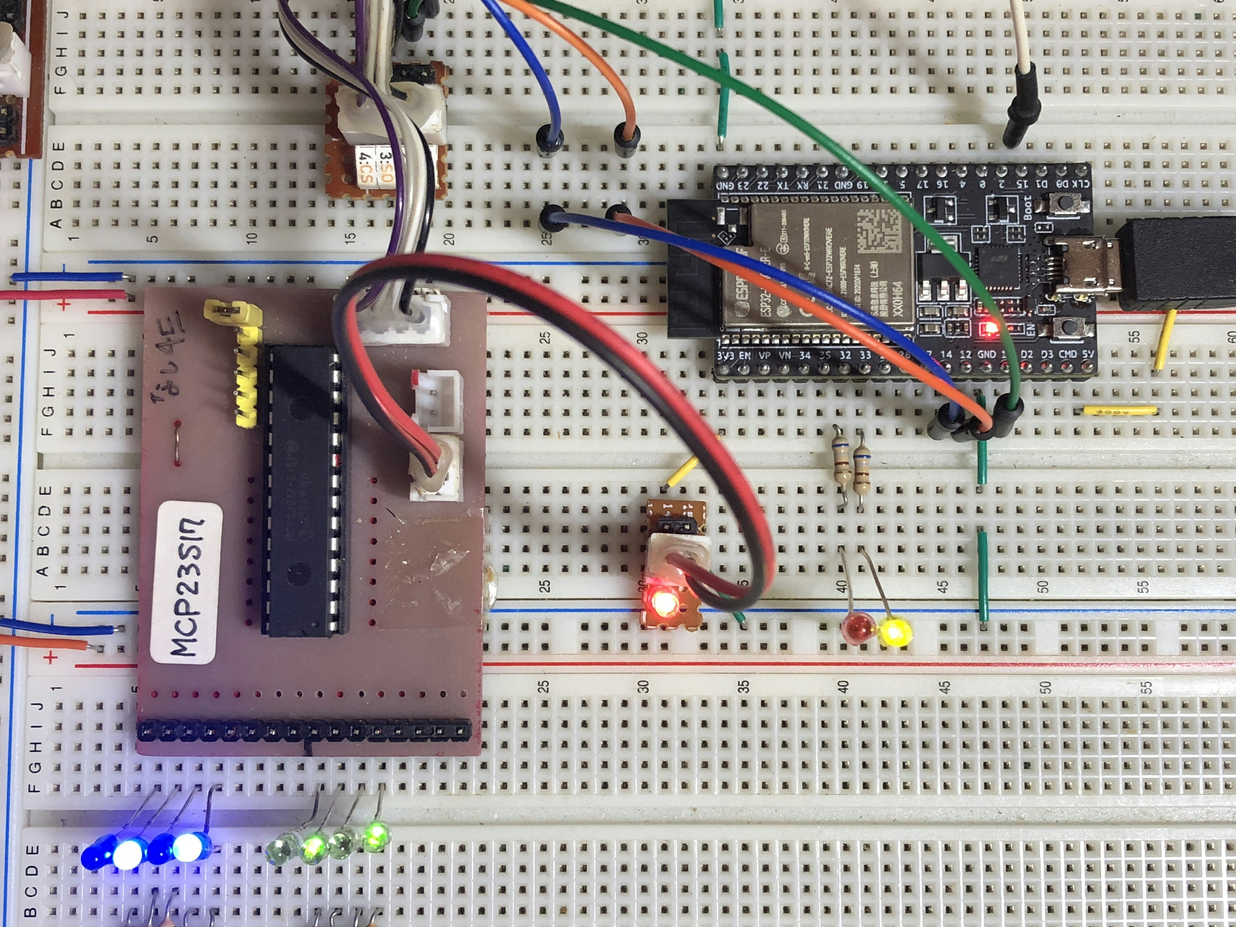
SPI IOエキスパンダーMCP23S17を対象にして、ESP-IDF driverでspi master通信を行いました。
環境
VScode+platformIO
platform = espressif32
board = my_esp32dev
framework = espidf
※ボードは、esp32devを修正した自作JSONファイル。
<参考>
SPIドライバー関連
本家Espressif解説
youtubeわかりやすいコード。
main.c
// Master SPI (VSPI) initiation

#include <stdio.h>
#include <stdlib.h>
#include <string.h>
#include "freertos/FreeRTOS.h"
#include "freertos/task.h"
#include "driver/spi_master.h"
#include "driver/gpio.h"
#include "sdkconfig.h"
#include "esp_log.h"

static const char TAG[] = "HSPI";

//OUTPUTピン Kconfig.projbuildに詳細設定
#define GPIO_OUTPUT_IO_0    CONFIG_GPIO_OUTPUT_0
#define GPIO_OUTPUT_IO_1    CONFIG_GPIO_OUTPUT_1
#define GPIO_OUTPUT_PIN_SEL  ((1ULL<<GPIO_OUTPUT_IO_0) | (1ULL<<GPIO_OUTPUT_IO_1))

void app_main(void)
{
    static bool val1,val2;
    val1=true;
    val2=false;
    //Output mode pin----------------------------
    //zero-initialize the config structure.
    gpio_config_t io_conf = {};
    //disable interrupt
    io_conf.intr_type = GPIO_INTR_DISABLE;
    //set as output mode
    io_conf.mode = GPIO_MODE_OUTPUT;
    //bit mask of the pins that you want to set,e.g.GPIO32/33
    io_conf.pin_bit_mask = GPIO_OUTPUT_PIN_SEL;
    //disable pull-down mode
    io_conf.pull_down_en = 0;
    //disable pull-up mode
    io_conf.pull_up_en = 0;
    //configure GPIO with the given settings
    gpio_config(&io_conf);


    ESP_LOGI(TAG,"spi_bus init");
    spi_bus_config_t buscfg =
    {
        .miso_io_num = 12,
        .mosi_io_num = 13,
        .sclk_io_num = 14,
        .quadwp_io_num = -1,
        .quadhd_io_num = -1,
        .max_transfer_sz = 32,
    };

    spi_device_interface_config_t devcfg =
    {
        .clock_speed_hz = 16*1000*1000, //16Mhz Clock out at 1 MHz with 1 us cycle
        .mode = 0,                 // SPI mode 0 - the clock signal starts with a low signal
        .spics_io_num = 15,        // CS pin
        .queue_size = 7,           // Queue 7 transactions at a time
    };

    // Initialize the SPI
    spi_bus_initialize(HSPI_HOST, &buscfg, 1);

    // Define SPI handle
    spi_device_handle_t spi2;
    spi_bus_add_device(HSPI_HOST, &devcfg, &spi2);

    // SPI transaction structure
    spi_transaction_t trans;
    memset(&trans, 0, sizeof(trans));
    trans.length = 8*3;              // length in bits
    int8_t test_str[] = {0x4E,0x0A,0xA8}; //MCP23S17 deviceAddress 0x4E
    trans.tx_buffer = &test_str;     // pointer to data to be transmitted
    spi_device_transmit(spi2, &trans);

    memset(&trans, 0, sizeof(trans));
    trans.length = 8*3;              // length in bits
    test_str[1]=0x00;
    test_str[2]=0x00;
    trans.tx_buffer = &test_str;     // pointer to data to be transmitted
    spi_device_transmit(spi2, &trans);

    memset(&trans, 0, sizeof(trans));
    trans.length = 8*3;              // length in bits
    test_str[1]=0x10;
    test_str[2]=0x00;
    trans.tx_buffer = &test_str;     // pointer to data to be transmitted
    spi_device_transmit(spi2, &trans);

    while (1)
    {
        memset(&trans, 0, sizeof(trans));
        trans.length = 8*3;              // length in bits
        test_str[1] = 0x0A;
        test_str[2] = 0x55;
        trans.tx_buffer = &test_str;     // pointer to data to be transmitted
        spi_device_transmit(spi2, &trans);

        memset(&trans, 0, sizeof(trans));
        trans.length = 8*3;              // length in bits
        test_str[1] = 0x1A;
        test_str[2] = 0x55;
        trans.tx_buffer = &test_str;     // pointer to data to be transmitted
        spi_device_transmit(spi2, &trans);

        gpio_set_level(GPIO_OUTPUT_IO_0,val1);
        gpio_set_level(GPIO_OUTPUT_IO_1,val2);
        val1=!val1;
        val2=!val2;
        printf("running\n");
        vTaskDelay(500 / portTICK_PERIOD_MS);              // Every 10 ms

        memset(&trans, 0, sizeof(trans));
        trans.length = 8*3;              // length in bits
        test_str[1] = 0x0A;
        test_str[2] = 0xAA;
        trans.tx_buffer = &test_str;     // pointer to data to be transmitted
        spi_device_transmit(spi2, &trans);

        memset(&trans, 0, sizeof(trans));
        trans.length = 8*3;
        test_str[1] = 0x1A;
        test_str[2] = 0xAA;
        trans.tx_buffer = &test_str;     // pointer to data to be transmitted
        spi_device_transmit(spi2, &trans);

        gpio_set_level(GPIO_OUTPUT_IO_0,val1);
        gpio_set_level(GPIO_OUTPUT_IO_1,val2);
        val1=!val1;
        val2=!val2;
        printf("running\n");
        vTaskDelay(500 / portTICK_PERIOD_MS);              // Every 10 ms
    }
}
kconfig.projbuild
menu "Example Configuration"

    config GPIO_OUTPUT_0
        int "GPIO output pin 0"
        range 0 39
        default 32
        help
            GPIO pin number to be used as GPIO_OUTPUT_IO_0.

    config GPIO_OUTPUT_1
        int "GPIO output pin 1"
        range 0 39
        default 33
        help
            GPIO pin number to be used as GPIO_OUTPUT_IO_1.

    config GPIO_INPUT_0
        int "GPIO input pin 0"
        range 0 39
        default 34
        help
            GPIO pin number to be used as GPIO_INPUT_IO_0.

    config GPIO_INPUT_1
        int "GPIO input pin 1"
        range 0 39
        default 35
        help
            GPIO pin number to be used as GPIO_INPUT_IO_1.

endmenu
platformio.ini
[env:my_esp32dev]
platform = espressif32
board = my_esp32dev
framework = espidf
board_upload.flashsize = 8MB
board_upload.maximum_size = 8388608
#build_flags = -DBOARD_HAS_PSRAM
board_upload.maximum_ram_size = 4536000
board_build.partitions = my_no_ota.csv
my_esp32dev.json
{
  "build": {
    "arduino":{
      "ldscript": "esp32_out.ld"
    },
    "core": "esp32",
    "extra_flags": "-DARDUINO_ESP32_DEV -DBOARD_HAS_PSRAM -mfix-esp32-psram-cache-issue",
    "f_cpu": "240000000L",
    "f_flash": "40000000L",
    "flash_mode": "dio",
    "mcu": "esp32",
    "variant": "esp32"
  },
  "connectivity": [
    "wifi",
    "bluetooth",
    "ethernet",
    "can"
  ],
  "debug": {
    "openocd_board": "esp-wroom-32.cfg"
  },
  "frameworks": [
    "arduino",
    "espidf"
  ],
  "name": "my ESP32 dev",
  "upload": {
    "flash_size": "8MB",
    "maximum_ram_size": 327680,
    "maximum_size": 8000000,
    "require_upload_port": true,
    "speed": 460800
  },
  "url": "https://en.wikipedia.org/wiki/ESP32",
  "vendor": "aki Espressif"
}