前回、I2C Host 通信について書きました。このときは内蔵オシレータMFINTOSC 500KHzをI2Cクロックソースに選択して、dividerの5で割った、100kHz がI2Cクロックになっていました。 100KHzでは遅いので、I2C標準の400KHzまで、速度を速めることにしました。
I2Cモジュールに入力するクロックソースを作る。
最終的にI2Cクロックスピードを、400kHzにするためには、その5倍の速度、2MHzのクロックソースを作り出す必要があります。
I2Cモジュールは入力されたクロックを4または5で割った周波数を使って運用されています。
18F27Q43には、自由にパルス周波数を調整してペリフェラルにわたせる、ちょうどいいモジュールがあります。
Reference Clock Output Module

設定はシンプルで、入力クロックソースを指定し、divide値とduty比を決定して、作りたい周波数のパルスをペリフェラルに渡すことができます。
今回は、Fosc=32MHzから2MHzのクロックをI2Cモジュールに渡したいので、divider=16 duty=50% クロックソースをFOSC=32MHzにしました。最後にENビットをONしたら、I2Cモジュールのクロックソースに2MHzのクロックが入力されます。
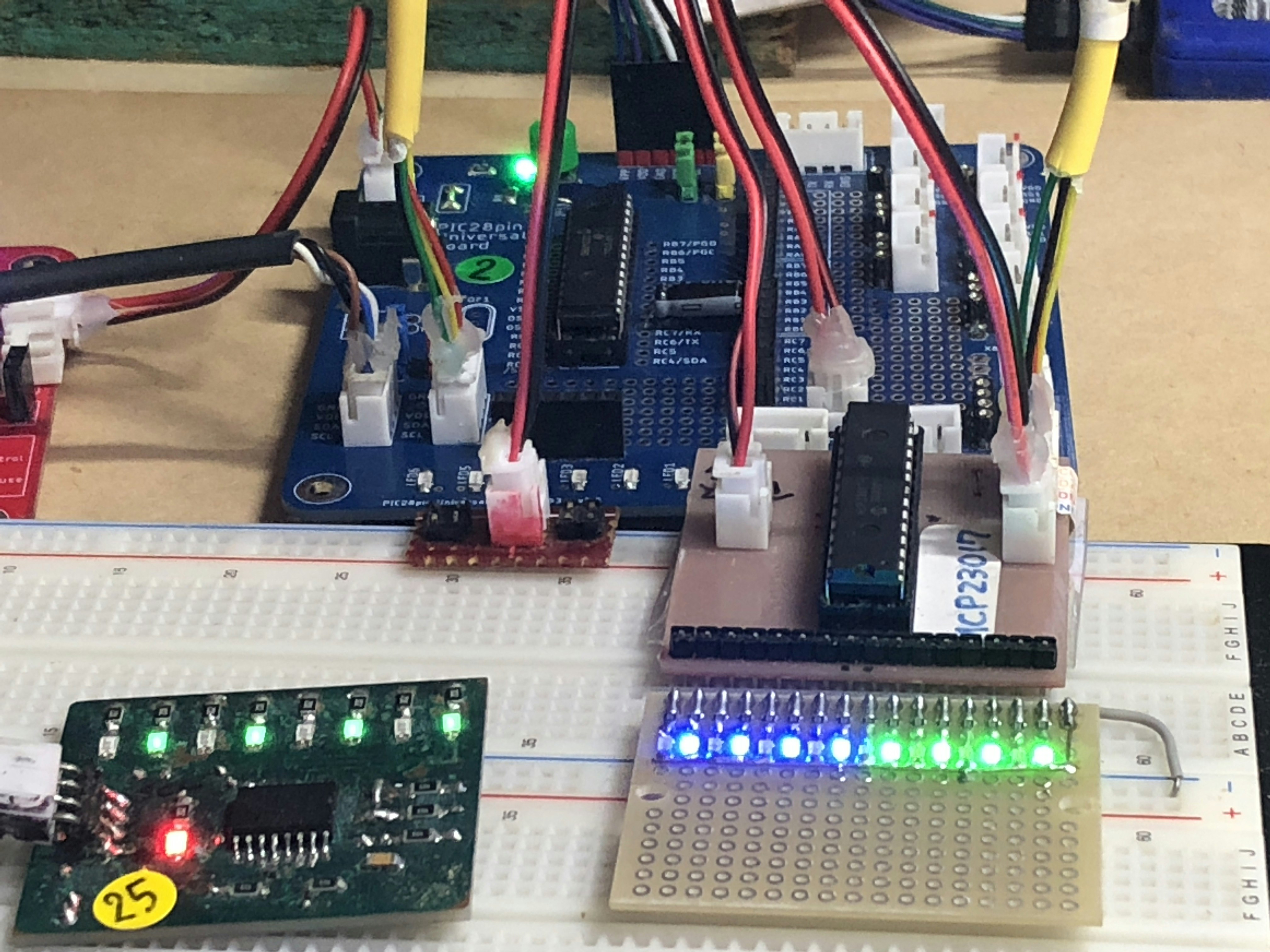
これで、前回、100kHz どまりだったスピードを400Khzにアップできました。
あとのI2Cモジュールの設定は、前回と同じです。
コード
Q_peripheral.c
//******************************************************//
// * Clock Reference Output 初期化
// *****************************************************//
void CLKREF_Init(void)
{
    CLKRCONbits.DC = 0b10; //duty 50%
    //CLKRCONbits.DIV = 0b110; //divided by 64 I2CCLK:0.5Mhz/5=100kHz
    //CLKRCONbits.DIV = 0b101; //divided by 32 I2CCLK:1Mhz/5=200kHz
    CLKRCONbits.DIV = 0b100; //divided by 16 I2CCLK:2Mhz/5=400kHz
    //CLKRCONbits.DIV = 0b011; //divided by  8 I2CCLK:4Mhz/5=800kHz
    CLKRCLK = 0b00000; //Sorce is Fosc
    CLKRCONbits.EN=1;
    __delay_ms(10);
}
Q_I2C1.h
#ifndef Q_I2C1_H
#define	Q_I2C1_H
#include <xc.h>
#include <stdio.h>
#include <stdlib.h>
#include <stdint.h>
#include <stdbool.h>
#include "Q_peripheral27Q43.h"

extern void I2C1_Init(void);
extern bool I2C1_b1Write(uint8_t _deviceAdd, uint8_t _data1);
extern uint8_t I2C1_b2Write(uint8_t _deviceAdd, uint8_t _data1, uint8_t _data2);
extern uint8_t I2C1_b1Read(uint8_t _deviceAdd,uint8_t _address);
#ifdef	__cplusplus
extern "C" {
#endif

#ifdef	__cplusplus
}
#endif

#endif	/* Q_I2C1_H */
Q_I2C1.c
#include <pic18f27q43.h>

#include "Q_I2C1.h"

uint8_t i2c1Cnt;
//*************************************************//
//** I2C1初期化
//*************************************************//
void I2C1_Init(void)
{
    //Set Clear Buffer Flag
    I2C1STAT1bits.CLRBF = 1;//I2Cバッファ、RXBF、TXBEビットクリア
    I2C1CON0bits.MODE=0b100;//Host mode, 7bits address
    I2C1CON1bits.ACKCNT=1;  //最終ACK確認で返す値0:ACK 1:NACK
    I2C1CON2bits.ABD=0;     //I2C1ADB0をアドレスバッファとして使用
    I2C1CON2bits.BFRET=0b00;//8clocksスタートになる準備パルス数
    I2C1CON2bits.FME = 1;   //Fi2cclk/5
  //I2C1CLK=0b0011;         //MFINTOSC500kHz//I2C用クロックソース
    I2C1CLK = 0b00100;      //Clock Reference Output//I2C用クロックソース400KHz
    I2C1PIR=0x00;           //I2C1専用割り込みフラグのクリア
    I2C1CON0bits.EN=1;      //I2C1モジュール有効
}
//*************************************************//
//** I2C1 1バイト送信
//*************************************************//
bool I2C1_b1Write(uint8_t _deviceAdd, uint8_t _data1)
{
    I2C1ADB1 = _deviceAdd;       //アドレスバッファにClientアドレスをセット
    I2C1CNT=1;                   //送信データ数をセット
    I2C1TXB=_data1;              //送信データを1バイトだけ、前もってセット
    I2C1CON0bits.S=1;            //Startコンディション
    while(!I2C1STAT0bits.BFRE);  //I2Cバスが解放されているか?
    while(!I2C1STAT1bits.TXBE);  //送信バッファが空か?(セットしたデータの送信完了)
    while(I2C1PIRbits.PC1IF==0); //Stopコンディションになったか?
    I2C1PIRbits.PC1IF=0;         //Stopフラグクリア
    while(I2C1STAT0bits.MMA);    //Host mode active を見て終了確認 0:not active 1:active
    //Set Clear Buffer Flag
    I2C1STAT1bits.CLRBF = 1;     //I2Cバッファ、RXBF,TXBEのクリア
    return true;
}

//*************************************************//
//** I2C1 2バイト送信
//*************************************************//
uint8_t I2C1_b2Write(uint8_t _deviceAdd, uint8_t _data1, uint8_t _data2)
{
    I2C1ADB1 = _deviceAdd;  //Clientデバイスアドレスセット
    I2C1CNT=2;              //送信データ数
    I2C1TXB=_data1;         //送信バッファに最初のデータをセット
    I2C1CON0bits.S=1;       //スタートコンディションセット

    while(!I2C1STAT0bits.BFRE)      //I2Cバスが解放されているか?
    {};
    while(I2C1STAT1bits.TXBE!=1)
    {};                             //最初のデータ送信完了?
    //while(!I2C1CON1bits.ACKSTAT);
    I2C1TXB=_data2;                 //次の送信データをセット
    while(I2C1STAT1bits.TXBE!=1);   //送信完了?
    while(I2C1PIRbits.PC1IF==0);    //ストップコンディション確定?
    I2C1PIRbits.PC1IF=0;            //ストップフラグクリア
    while(I2C1STAT0bits.MMA);       //Host mode Active確認 0:not Active 1:active
    //Set Clear Buffer Flag
    I2C1STAT1bits.CLRBF = 1;        //I2C1バッファ、TXBE,RXBFクリア
    return true;
}

//*************************************************//
//** I2C1 1バイト受信
//*************************************************//
uint8_t I2C1_b1Read(uint8_t _deviceAdd,uint8_t _address)
{
    uint8_t ret;
    I2C1ADB1 = _deviceAdd;          //Clientアドレスセット
    I2C1CNT=1;                      //送信バイト数(この場合は、引数の_address)
    I2C1TXB=_address;               //送信バイトセット
    I2C1CON0bits.S=1;               //Startコンディションセット
    while(!I2C1STAT0bits.BFRE);     //I2Cバス解放?確認
    while(I2C1STAT1bits.TXBE!=1);   //送信バッファ 0:full 1:empty 送信完了確認
    //リスタート
    I2C1CON0bits.RSEN=1;            //リスタート開始
     while(!I2C1CON0bits.MDR);      //RSENセットで1になる。
    I2C1CON0bits.S=1;               //Startコンディションセット
    I2C1ADB1 = _deviceAdd|0x01;     //Clientアドレス+R/Wビット
    I2C1CNT=1;                      //読み出し数
    while(!I2C1STAT1bits.RXBF);     //読み込み完了待ち?
    ret=I2C1RXB;                    //バッファから読み出し
    I2C1CON0bits.RSEN=0;            //リスタート解除
    I2C1PIR=0x00;                   //PIRクリア
    while(I2C1STAT0bits.MMA);       //HostmodeActime 0:not Active 1:active
    //Set Clear Buffer Flag
    I2C1STAT1bits.CLRBF = 1;        //I2C1バッファクリア
    return ret;
}
main.c
/*
 * File:   main.c
 * Author: yutak
 *
 * Created on 2022/12/29, 18:47
 */


// PIC18F27Q43 Configuration Bit Settings

// 'C' source line config statements

// CONFIG1
#pragma config FEXTOSC = OFF    // External Oscillator Selection (Oscillator not enabled)
#pragma config RSTOSC = HFINTOSC_64MHZ// Reset Oscillator Selection (HFINTOSC with HFFRQ = 64 MHz and CDIV = 1:1)

// CONFIG2
#pragma config CLKOUTEN = OFF   // Clock out Enable bit (CLKOUT function is disabled)
#pragma config PR1WAY = OFF     // PRLOCKED One-Way Set Enable bit (PRLOCKED bit can be set and cleared repeatedly)
#pragma config CSWEN = ON       // Clock Switch Enable bit (Writing to NOSC and NDIV is allowed)
#pragma config FCMEN = OFF      // Fail-Safe Clock Monitor Enable bit (Fail-Safe Clock Monitor disabled)

// CONFIG3
#pragma config MCLRE = EXTMCLR  // MCLR Enable bit (If LVP = 0, MCLR pin is MCLR; If LVP = 1, RE3 pin function is MCLR )
#pragma config PWRTS = PWRT_OFF // Power-up timer selection bits (PWRT is disabled)
#pragma config MVECEN = ON      // Multi-vector enable bit (Multi-vector enabled, Vector table used for interrupts)
#pragma config IVT1WAY = ON     // IVTLOCK bit One-way set enable bit (IVTLOCKED bit can be cleared and set only once)
#pragma config LPBOREN = OFF    // Low Power BOR Enable bit (Low-Power BOR disabled)
#pragma config BOREN = SBORDIS  // Brown-out Reset Enable bits (Brown-out Reset enabled , SBOREN bit is ignored)

// CONFIG4
#pragma config BORV = VBOR_1P9  // Brown-out Reset Voltage Selection bits (Brown-out Reset Voltage (VBOR) set to 1.9V)
#pragma config ZCD = OFF        // ZCD Disable bit (ZCD module is disabled. ZCD can be enabled by setting the ZCDSEN bit of ZCDCON)
#pragma config PPS1WAY = OFF     // PPSLOCK bit One-Way Set Enable bit (PPSLOCKED bit can be cleared and set only once; PPS registers remain locked after one clear/set cycle)
#pragma config STVREN = ON      // Stack Full/Underflow Reset Enable bit (Stack full/underflow will cause Reset)
#pragma config LVP = ON         // Low Voltage Programming Enable bit (Low voltage programming enabled. MCLR/VPP pin function is MCLR. MCLRE configuration bit is ignored)
#pragma config XINST = OFF      // Extended Instruction Set Enable bit (Extended Instruction Set and Indexed Addressing Mode disabled)

// CONFIG5
#pragma config WDTCPS = WDTCPS_31// WDT Period selection bits (Divider ratio 1:65536; software control of WDTPS)
#pragma config WDTE = OFF       // WDT operating mode (WDT Disabled; SWDTEN is ignored)

// CONFIG6
#pragma config WDTCWS = WDTCWS_7// WDT Window Select bits (window always open (100%); software control; keyed access not required)
#pragma config WDTCCS = SC      // WDT input clock selector (Software Control)

// CONFIG7
#pragma config BBSIZE = BBSIZE_512// Boot Block Size selection bits (Boot Block size is 512 words)
#pragma config BBEN = OFF       // Boot Block enable bit (Boot block disabled)
#pragma config SAFEN = OFF      // Storage Area Flash enable bit (SAF disabled)
#pragma config DEBUG = OFF      // Background Debugger (Background Debugger disabled)

// CONFIG8
#pragma config WRTB = OFF       // Boot Block Write Protection bit (Boot Block not Write protected)
#pragma config WRTC = OFF       // Configuration Register Write Protection bit (Configuration registers not Write protected)
#pragma config WRTD = OFF       // Data EEPROM Write Protection bit (Data EEPROM not Write protected)
#pragma config WRTSAF = OFF     // SAF Write protection bit (SAF not Write Protected)
#pragma config WRTAPP = OFF     // Application Block write protection bit (Application Block not write protected)

// CONFIG10
#pragma config CP = OFF         // PFM and Data EEPROM Code Protection bit (PFM and Data EEPROM code protection disabled)

// #pragma config statements should precede project file includes.
// Use project enums instead of #define for ON and OFF.

#include <xc.h>
#include <stdio.h>
#include <stdlib.h>
#include <stdint.h>
#include <stdbool.h>
#include "Q_peripheral27Q43.h"
#include "Q_interrupt27Q43.h"
#include "Q_initialize.h"
#include "Q_I2C1.h"
#include "I2C_LCD.h"
#include "stringFormat.h"

void portInit(void);
void oscillatorInit(void);
void vicInit(void);
uint8_t ret[5];
void main(void)
{
    uint8_t val, i;
    //CPUハード初期化-------------------------------
    portInit();         //port初期化
    oscillatorInit();   //オシレータ初期化Fosc=32MHz
    vicInit();          //ベクターテーブル初期化

    //周辺機能初期化--------------------------------
    usartInit();
    printf("START I2C\n");
    CLKREF_Init();
    I2C1_Init();
    //MCP23017初期化-------------------------------
    I2C1_b2Write(0x4C,0x0A,0x80);
    I2C1_b2Write(0x4C,0x00,0x00);
    I2C1_b2Write(0x4C,0x09,0x00);
    I2C1_b2Write(0x4C,0x0A,0x00);
    I2C1_b2Write(0x4C,0x10,0x00);
    I2C1_b2Write(0x4C,0x19,0x00);
    I2C1_b2Write(0x4C,0x1A,0x00);
    //MCP23017初期化値シリアル出力------------------
    for(i=0; i<=0x0A; i++)
    {
        val=I2C1_b1Read(0x4C,i);
        printf("[%x]=%x\n",i,val);
    }
     for(i=0x10; i<=0x1A; i++)
    {
        val=I2C1_b1Read(0x4C,i);
        printf("[%x]=%x\n",i,val);
    }

    while(1)
    {
        __delay_ms(500);
        I2C1_b1Write(0x4A,0x55);        //PCF8574
        I2C1_b2Write(0x4C,0x0A,0xAA);   //MCP23017 portA
        I2C1_b2Write(0x4C,0x1A,0xAA);   //MCP23017 portB

        __delay_ms(500);
        I2C1_b1Write(0x4A,0xAA);        //PCF8574
        I2C1_b2Write(0x4C,0x0A,0x55);   //MCP23017 portA
        I2C1_b2Write(0x4C,0x1A,0x55);   //MCP23017 portB

    }
    return;
}

void oscillatorInit(void)
{
    //オシレータ設定----------------
    OSCCON3bits.CSWHOLD=1;//Hold
    OSCCON1bits.NDIV=1;//64Mhz/2=32Mhz;
    while(!OSCCON3bits.NOSCR);
    while(!PIR0bits.CSWIF);//ready state
    PIR0bits.CSWIF=0;
    OSCCON3bits.CSWHOLD=0;
    while(!OSCCON3bits.ORDY);
}

void portInit(void)
{
    //ポート設定----------------------
    PORTA=0x00;
    LATA=0x00;
    ANSELA=0x00;
    TRISA=0x00;

    PORTB=0x00;
    LATB=0x00;
    ANSELB=0x00;
    TRISB=0x00;

    PORTC=0x00;
    LATC=0x00;
    ANSELC=0x00;
    TRISC=0x00;

     //PPS---------------------
    PPSLOCK = 0x55;
    PPSLOCK = 0xAA;
    PPSLOCKbits.PPSLOCKED = 0;

    //I2C1-------------------------
    //RC4 for SDA
    RC4PPS=0x38;
    I2C1SDAPPS=0x14;
    //RC3 for SCL
    RC3PPS = 0x37;
    I2C1SCLPPS=0x13;

    PPSLOCK = 0x55;
    PPSLOCK = 0xAA;
    PPSLOCKbits.PPSLOCKED = 1;

    ODCONCbits.ODCC3=1;
    ODCONCbits.ODCC4=1;

    RC3I2Cbits.TH=1;
    RC4I2Cbits.TH=1;

}

void vicInit(void)
{
 //割り込みテーブルaddress設定----------------------------------
    INTCON0bits.GIE=0;//Enable all masked interrupts
    IVTLOCK=0x55;
    IVTLOCK=0xAA;
    IVTLOCKbits.IVTLOCKED=0;
    IVTBASE = 0x000008;
    IVTLOCK=0x55;
    IVTLOCK=0xAA;
    IVTLOCKbits.IVTLOCKED=1;
}