PIC32MX I2Cドライバー
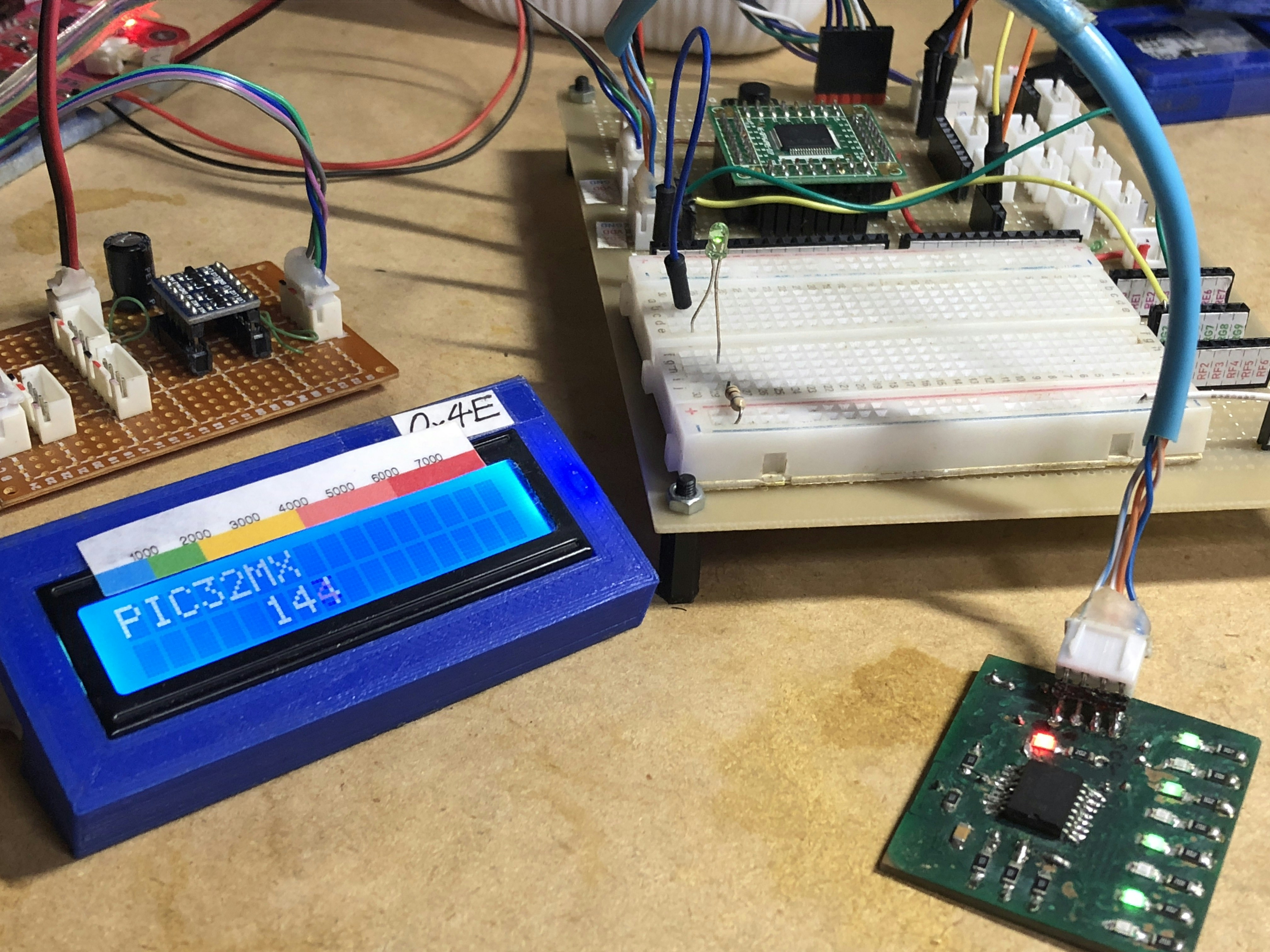
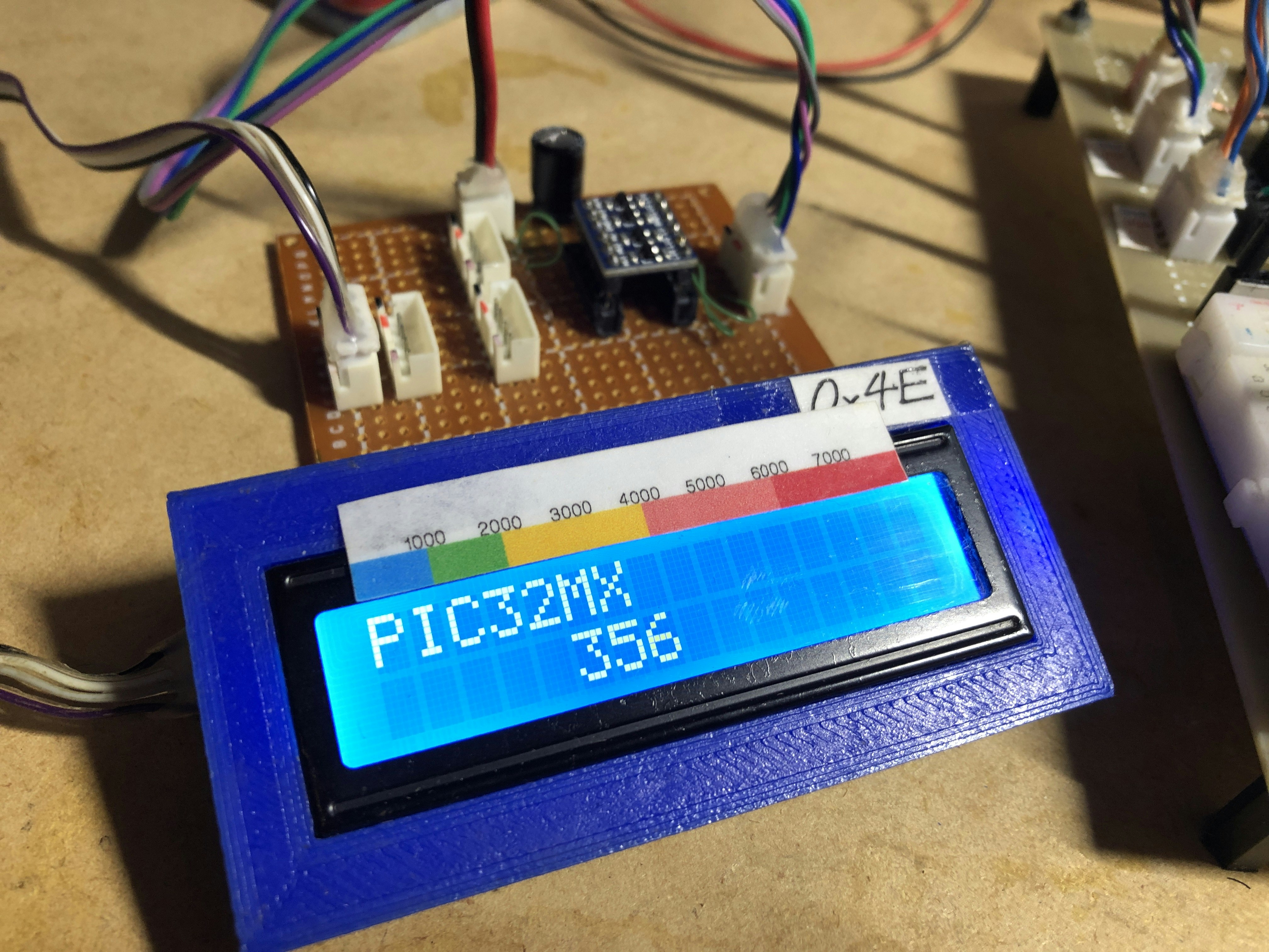

左:2行16文字LCD:PCF8574 IOエキスパンダーで制御(5v駆動)
3.3Vから5Vにレベル変換して通信。
右:PCF8574 IOエキスパンダー基板
この2つのI2Cデバイスを動かしました。
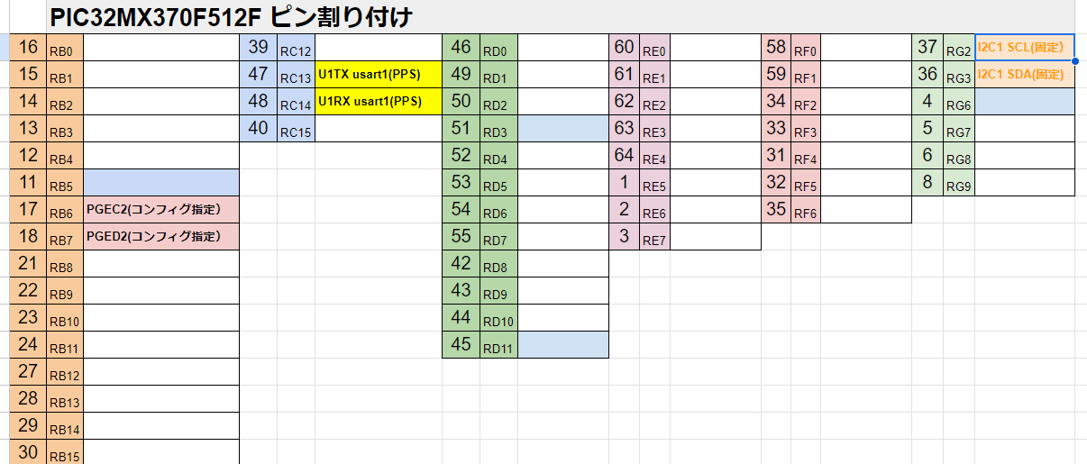
PIC32 I2C1ドライバー
PIC32 28pinで動いたものを、64pinに移植。
変更点は、クロック線とデータ線のピン位置のみ。で、動いた。
クロックスピードを初期化時は、100khzに設定。LCDの初期化終了時に、600khzにする。LCDの初期化時、400khz以上にすると、LCDが初期化されないため。
I2Cのレジスタ操作は、dsPICで制作したものを移植。2年以上まえなので、詳細は忘れたが、動き自体は、大差なかったはず。レジスタ名の変更で行けたはず。
PIC32_I2C1.h
#ifndef PIC32_I2C1_H
#define	PIC32_I2C1_H

#ifdef	__cplusplus
extern "C" {
#endif

#include <xc.h>
#include <cp0defs.h>
#include <sys/attribs.h>
#include <stdio.h>
#include <stdbool.h>
//デバイスアドレス
#define MCP4726DeviceAdd 0xC0

#define I2C1_Ack   0//SSP1CON2.ACKDT master:receive mode
#define I2C1_NoAck 1//SSP1CON2.ACKDT master:receive mode

#define I2C1_SCL_PIN PORTGbits.RG2
#define I2C1_SDA_PIN PORTGbits.RG3

extern void I2C1_Init(void);
extern void I2C1_Reset(void);
extern bool I2C1_CheckIdle(void);
extern bool I2C1_ClearIF(void);
extern bool I2C1_Start(void);
extern bool I2C1_ReStart(void);
extern bool I2C1_Stop(void);
extern bool I2C1_Tx_Buffer_Write(uint8_t  _data);
extern uint8_t I2C1_Rx_Buffer_Read(void);
extern bool I2C1_Wait_Ack(void);
extern bool I2C1_Send_Ack(uint8_t _Ack_Nack);

typedef struct{
    unsigned int cnt;
    bool fg;
}_I2CError;
extern _I2CError I2C1Error;
extern uint8_t I2C1_DataBuffer[10];
//------------------------------------------------------------------------
extern uint8_t I2C1_b1Write(uint8_t _device_add, uint8_t _data);
extern uint8_t I2C1_b2Write(uint8_t _device_add, uint8_t _data1, uint8_t _data2);
extern bool I2C1_bnWrite(uint8_t _device_add, uint8_t *_data, uint8_t _len);
extern bool I2C1_bnWrite1(uint8_t _device_add, uint8_t _add, uint8_t *_data, uint8_t _len);
extern bool I2C1_bnWriteSV(uint8_t _device_add, uint8_t _add, uint8_t _val, uint8_t _len);
extern uint8_t I2C1_b1Read(uint8_t _device_add, uint8_t _data1);
extern bool I2C1_bnRead(uint8_t _device_add, uint8_t _data1,uint8_t _len);
#ifdef	__cplusplus
}
#endif

#endif	/* PIC32_I2C1 */
PIC32_I2C1.c
//
//220812 b1Read最後のNack修正。

#include "PIC32_I2C1driver.h"
#include "peripheral.h"
_I2CError I2C1Error;
uint8_t I2C1_DataBuffer[10];

void I2C1_Init(void)
{
    unsigned int i;

    I2C1CON=0x0000;

    //I2C1BRG=0x002F;//400kHz Fp=40Mhz
    I2C1BRG=0x0189;//100khz Fp=80Mhz
    I2C1CONbits.DISSLW=1;//errata
    I2C1CONbits.STREN=1;
    I2C1CONbits.ON=1;

    IFS1bits.I2C1MIF=0;
    IEC1bits.I2C1MIE=0;
    IFS1bits.I2C1SIF=0;
    IEC1bits.I2C1SIE=0;
}

void I2C1_Reset(void)
{
    unsigned int buf;
    I2C1CONbits.I2CEN=0;
    buf=TRISB;
    buf|=0x0000;
    I2C1_SCL_PIN=0;
    __delay_us(10);
    I2C1_SCL_PIN=1;
    __delay_us(10);
    I2C1_SCL_PIN=0;
    __delay_us(10);
    I2C1_SCL_PIN=1;
    __delay_us(10);
}

bool I2C1_CheckIdle(void)
{
    signed int i;
    unsigned int buf;

    for(i=0x7FFF; i; i--)
    {
        buf=I2C1CON;
        //buf&=0x44DB;
        buf&=0x003F;
        if(!buf)
            return true;
    }
    return false;
}

bool I2C1_ClearIF(void)
{
    signed int i;
    for(i=0x3FFF; i; i--)
    {
        if(IFS1bits.I2C1MIF)
        {
            IFS1bits.I2C1MIF=0;
            return true;
        }
    }
    return false;
}

bool I2C1_Start(void)
{
    signed int i;

    for(i=0x3FFF; i; i--)
    {
        if(I2C1_CheckIdle())
        {
            I2C1CONbits.SEN=1;
            if(I2C1_ClearIF());
                return true;
        }
    }
    return false;
}

bool I2C1_ReStart(void)
{
     //restart
    signed int i;
    for(i=0x3FFF; i; i--)
    {
        if(I2C1_CheckIdle())
        {
            I2C1CONbits.RSEN=1;
            return true;
        }
    }
    return false;
}

bool I2C1_Stop(void)
{
    signed int i;
    for(i=0x3FFF; i; i--)
    {
        if(I2C1_CheckIdle())
        {
            I2C1CONbits.PEN=1;
            while(I2C1CONbits.PEN);
            if(I2C1_ClearIF())
                return true;
        }
    }
    return false;

}

//I2C1 transmit register write
//TBS: 0:empty 1:I2C1TRN full
bool I2C1_Tx_Buffer_Write(uint8_t _data)
{
    signed int i,j;

    if(!I2C1_CheckIdle())return false;
    I2C1TRN=_data;
    for(i=0x7FFF; i; i--)
    {
        if(!I2C1STATbits.TBF)
        {
            while(I2C1STATbits.TRSTAT)
            {
                j++;
                if(j>0x7FFF)return false;
            };
            return true;
        }
    }
    return false;
}

uint8_t I2C1_Rx_Buffer_Read(void)
{
    uint8_t ret,cnt;
    ret=0xFF;
    cnt=0;
    if(!I2C1_CheckIdle())return false;
    I2C1CONbits.RCEN=1;
    while(!I2C1STATbits.RBF){
         __delay_us(3);
        cnt++;
        if(cnt==200)return false;
    };
    //if(!I2C1_CheckIdle())return false;
    ret = I2C1RCV;
    return ret;
}
//ACKSTAT 0:ACK 1:NACK
bool I2C1_Wait_Ack(void)
{
    signed int i;
    for(i=0x7FFF; i; i--)
    {
        if(!I2C1STATbits.ACKSTAT)
            return true;
    }
    return false;
}

bool I2C1_Send_Ack(uint8_t _Ack_Nack)
{
    if(!I2C1_CheckIdle())return false;
    I2C1CONbits.ACKDT=_Ack_Nack;
    I2C1CONbits.ACKEN=1;
    while(I2C1CONbits.ACKEN);
    I2C1CONbits.ACKDT=0;//220812追記
    if(!I2C1_ClearIF()) return false;
    return true;
}
//------------------------------------------------------------------------
uint8_t I2C1_b1Write(uint8_t _device_add, uint8_t _data)
{
    //start condition
    I2C1_Start();
    //send device address
    I2C1_Tx_Buffer_Write(_device_add);
    if(!I2C1_Wait_Ack())
        return 0xE1;
    if(!I2C1_ClearIF())
        return 0xE2;
    //send data
    I2C1_Tx_Buffer_Write(_data);
    if(!I2C1_Wait_Ack())
        return 0xE3;
    if(!I2C1_ClearIF())
        return 0xE4;
    //Stop condition
    I2C1_Stop();
    return true;
}

bool I2C1_bnWrite(uint8_t _device_add, uint8_t *_data, uint8_t _len)
{
    uint8_t buf;
    //start condition
    I2C1_Start();
    //send device address
    I2C1_Tx_Buffer_Write(_device_add);
     if(!I2C1_Wait_Ack())
        return false;
    if(!I2C1_ClearIF())
        return false;

    //send data
    do{
        buf=*_data;
        I2C1_Tx_Buffer_Write(buf);
        if(!I2C1_Wait_Ack())
            return false;
        if(!I2C1_ClearIF())
        return false;
        _data++;
        _len--;
    }while(_len!=0);
    //Stop condition
    I2C1_Stop();
    return true;
}

uint8_t I2C1_b2Write(uint8_t _device_add, uint8_t _data1, uint8_t _data2)
{
    //start condition
    I2C1_Start();
    //send device address-----------------
    I2C1_Tx_Buffer_Write(_device_add);
    if(!I2C1_Wait_Ack())
    {
        return 0x41;
    }
    if(!I2C1_ClearIF())
    {
        return 0x42;
    }
    //send data1------------------------
    I2C1_Tx_Buffer_Write(_data1);
    if(!I2C1_Wait_Ack())
    {
        return 0x43;
        //return false;
    }
    if(!I2C1_ClearIF())
        return 0x44;
        //send data
    //send data2------------------------
    I2C1_Tx_Buffer_Write(_data2);
    if(!I2C1_Wait_Ack())
    {
        return 0x45;
    }
    if(!I2C1_ClearIF())
    {
        return 0x46;
    }
    //Stop condition
    I2C1_Stop();
    return true;
}

bool I2C1_bnWrite1(uint8_t _device_add, uint8_t _add, uint8_t *_data, uint8_t _len)
{
    uint8_t buf;
    //start condition
    I2C1_Start();
    //send device address
    I2C1_Tx_Buffer_Write(_device_add);
     if(!I2C1_Wait_Ack())
        return false;
    if(!I2C1_ClearIF())
        return false;
    I2C1_Tx_Buffer_Write(_add);
     if(!I2C1_Wait_Ack())
        return false;
    if(!I2C1_ClearIF())
        return false;
    //send data
    do{
        buf=*_data;
        I2C1_Tx_Buffer_Write(buf);
        if(!I2C1_Wait_Ack())
            return false;
        if(!I2C1_ClearIF())
        return false;
        _data++;
        _len--;
    }while(_len!=0);
    //Stop condition
    I2C1_Stop();
    return true;
}

bool I2C1_bnWriteSV(uint8_t _device_add, uint8_t _add, uint8_t _val, uint8_t _len)
{
    uint8_t buf;
    //start condition
    I2C1_Start();
    //send device address
    I2C1_Tx_Buffer_Write(_device_add);
     if(!I2C1_Wait_Ack())
        return false;
    if(!I2C1_ClearIF())
        return false;
    I2C1_Tx_Buffer_Write(_add);
     if(!I2C1_Wait_Ack())
        return false;
    if(!I2C1_ClearIF())
        return false;
    //send data
    do{
        I2C1_Tx_Buffer_Write(_val);
        if(!I2C1_Wait_Ack())
            return false;
        if(!I2C1_ClearIF())
        return false;
        _len--;
    }while(_len!=0);
    //Stop condition
    I2C1_Stop();
    return true;
}

uint8_t I2C1_b1Read(uint8_t _device_add, uint8_t _data1)
{
    uint8_t ret;
    //Start Condition
    I2C1_Start();
     //send device address
    ret=I2C1_Tx_Buffer_Write(_device_add);
    if(!I2C1_Wait_Ack())
    {
        return 0xA0;
    }
    if(!I2C1_ClearIF())
    {
        return 0xA1;
    }

    //send data
    I2C1_Tx_Buffer_Write(_data1);
    if(!I2C1_Wait_Ack())
    {
        return 0xA2;
    }
    if(!I2C1_ClearIF())
    {
        return 0xA3;
    }
    //restart
    I2C1_ReStart();
    if(!I2C1_ClearIF())
    {
        return 0xA4;
    }
      //send device address
    I2C1_Tx_Buffer_Write(_device_add|0x01);
    if(!I2C1_Wait_Ack())
    {
        return 0xA5;
    }
    if(!I2C1_ClearIF())
    {
        return 0xA6;
    }
    //recieve data
    ret=I2C1_Rx_Buffer_Read();
    if(!I2C1_ClearIF())
    {
        return 0xA7;
    }
    //send Nack
    I2C1_Send_Ack(I2C1_NoAck);
   /* if(!I2C1_ClearIF())
    {
        return 0xA2;
    }*/
    //Stop Condition
    I2C1_Stop();
  /*  if(!I2C1_ClearIF())
    {
        return 0xA3;
    }*/

    return ret;
}

bool I2C1_bnRead(uint8_t _device_add, uint8_t _data1,uint8_t _len)
{
    uint8_t index=0;
     //Start Condition
    I2C1_Start();
     //send device address
    I2C1_Tx_Buffer_Write(_device_add);
    if(!I2C1_Wait_Ack())
    {
        return 0xA0;
    }
    if(!I2C1_ClearIF())
    {
        return 0xA1;
    }

    //send data
    I2C1_Tx_Buffer_Write(_data1);
    if(!I2C1_Wait_Ack())
    {
        return 0xA2;
    }
    if(!I2C1_ClearIF())
    {
        return 0xA3;
    }
    //restart
    I2C1_ReStart();
    if(!I2C1_ClearIF())
    {
        return 0xA4;
    }
      //send device address
    I2C1_Tx_Buffer_Write(_device_add|0x01);
    if(!I2C1_Wait_Ack())
    {
        return 0xA5;
    }
    if(!I2C1_ClearIF())
    {
        return 0xA6;
    }
    //recieve data
    do{
        I2C1_DataBuffer[index++]=I2C1_Rx_Buffer_Read();
        if(!I2C1_ClearIF())
        {
            return 0xA7;
        }
        if(_len!=1)
        {
            I2C1_Send_Ack(I2C1_Ack);
        }
        _len--;
    }while(_len!=0);

    //send Nack
    I2C1_Send_Ack(I2C1_NoAck);

    I2C1_Stop();
    return true;
}
LCDドライバー
I2C_LCD.h
#ifndef I2C_LCD_H
#define	I2C_LCD_H

#ifdef	__cplusplus
extern "C" {
#endif


#include <xc.h>
#include <cp0defs.h>
#include <sys/attribs.h>
#include <stdio.h>
#include <stdbool.h>
#include "PIC32_I2C1driver.h"
#include "peripheral.h"


#define CM	0	//Command Mode
#define DM	1	//Data Mode
#define WM  0	//出力WriteMode
#define RM  1   //入力ReadMode
#define High 1
#define Low  0
#define LED_ON 1
#define LED_OFF 0
#define LcdDeviceAdd 0x4E//FC-113(RCF8574 address)
#define LcdDeviceAdd_AT 0x7E//RCF8574AT address

#define LcdDDRAMAdd_firstline 0x80
#define LcdDDRAMAdd_secondline 0xC0
#define LcdDDRAMAdd_thirdline 0x94
#define LcdDDRAMAdd_forthline 0xD4
#define LcdCmd_Clear_all 0x01

extern uint8_t LCD_BackLight_EN[2];
typedef union {
	uint8_t byt;
	struct{
		uint8_t RS:1;//LSB
		uint8_t RW:1;
		uint8_t EN:1;
		uint8_t LED:1;
		uint8_t D4:1;
		uint8_t D5:1;
		uint8_t D6:1;
		uint8_t D7:1;//MSB
	};
}_OD;
extern _OD OD;
extern char LCDTxt[16];

extern void LCD_send(uint8_t _device_add,uint8_t _data, uint8_t _mode);
extern void LCD_WriteData(uint8_t _device_add,uint8_t data);
extern void LCD_Command(uint8_t _device_add,uint8_t cmd);
extern void LCD_Init(uint8_t _device_add);
extern void LCD_Printf(uint8_t _device_add, uint8_t *string, uint8_t _length, uint8_t _DDRAM_Add);


#ifdef	__cplusplus
}
#endif

#endif	/* I2C_LCD_H */
I2C_LCD.c
#include "I2C_LCD.h"
uint8_t LCD_BackLight_EN[2];
_OD OD;
 char LCDTxt[16];
//-----------------------------------------//
//LCD_send
//_device_add
//data: Upper 4bits data
//_mode: CM 0 :Command Mode
//		   DM 1 :Data Mode
//_led on/off
//-----------------------------------------//
void LCD_send(uint8_t _device_add,uint8_t _data, uint8_t _mode)
{
    OD.byt=0x00;
    if(_device_add==LcdDeviceAdd_AT)
          OD.LED=LCD_BackLight_EN[0];
    else
          OD.LED=LCD_BackLight_EN[1];

    OD.byt = OD.byt|(_data& 0xF0);
    I2C1_b1Write(_device_add,OD.byt);
    __delay_us(300);
    OD.RS=_mode;
    I2C1_b1Write(_device_add,OD.byt);
    __delay_us(300);
    OD.EN=High;
    I2C1_b1Write(_device_add,OD.byt);
    __delay_us(300);
    OD.EN=Low;
    I2C1_b1Write(_device_add,OD.byt);
    __delay_us(300);
}

void LCD_WriteData(uint8_t _device_add,uint8_t _data)
{
    LCD_send(_device_add, _data,DM);
    LCD_send(_device_add, _data<<4,DM);
    __delay_us(40);
}

void LCD_Command(uint8_t _device_add,uint8_t cmd)
{
    LCD_send(_device_add,cmd,CM);
    LCD_send(_device_add,cmd<<4,CM);
    __delay_us(40);
}

void LCD_Init(uint8_t _device_add)
{
    __delay_ms(15);
    LCD_send(_device_add,0x30,CM);//8bits mode
    __delay_ms(5);
    LCD_send(_device_add,0x30,CM);//8bits mode
	__delay_us(500);
	LCD_send(_device_add,0x30,CM);//8bits mode three times setting
	LCD_send(_device_add,0x20,CM);//4bits mode
	LCD_Command(_device_add,0x28);//Function setting.
	LCD_Command(_device_add,0x08);//display off
	LCD_Command(_device_add,0x01);//display clear
	LCD_Command(_device_add,0x06);//entry
	LCD_Command(_device_add,0x02);//cursor home
	LCD_Command(_device_add,0x0C);//display on

    LCD_BackLight_EN[0]=LED_ON;
    LCD_BackLight_EN[1]=LED_ON;
}

//
//
void LCD_Printf(uint8_t _device_add, uint8_t *string, uint8_t _length, uint8_t _DDRAM_Add)
{
    LCD_Command(_device_add,_DDRAM_Add);
    do{
        LCD_WriteData(_device_add, *string);
        string++;
    }while(--_length);
}
main.c
main.c
// PIC32MX370F512H Configuration Bit Settings

// 'C' source line config statements

// DEVCFG3
#pragma config USERID = 0xFFFF          // Enter Hexadecimal value (Enter Hexadecimal value)
#pragma config FSRSSEL = PRIORITY_7     // Shadow Register Set Priority Select (SRS Priority 7)
#pragma config PMDL1WAY = OFF           // Peripheral Module Disable Configuration (Allow multiple reconfigurations)
#pragma config IOL1WAY = OFF            // Peripheral Pin Select Configuration (Allow multiple reconfigurations)

// DEVCFG2
#pragma config FPLLIDIV = DIV_2         // PLL Input Divider (2x Divider)
#pragma config FPLLMUL = MUL_20         // PLL Multiplier (20x Multiplier)
#pragma config FPLLODIV = DIV_2         // System PLL Output Clock Divider (PLL Divide by 1)

// DEVCFG1
#pragma config FNOSC = FRCPLL           // Oscillator Selection Bits (Fast RC Osc with PLL)
#pragma config FSOSCEN = OFF            // Secondary Oscillator Enable (Disabled)
#pragma config IESO = OFF               // Internal/External Switch Over (Disabled)
#pragma config POSCMOD = OFF            // Primary Oscillator Configuration (Primary osc disabled)
#pragma config OSCIOFNC = OFF           // CLKO Output Signal Active on the OSCO Pin (Disabled)
#pragma config FPBDIV = DIV_1           // Peripheral Clock Divisor (Pb_Clk is Sys_Clk/1)
#pragma config FCKSM = CSECMD           // Clock Switching and Monitor Selection (Clock Switch Enable, FSCM Disabled)
#pragma config WDTPS = PS1048576        // Watchdog Timer Postscaler (1:1048576)
#pragma config WINDIS = OFF             // Watchdog Timer Window Enable (Watchdog Timer is in Non-Window Mode)
#pragma config FWDTEN = OFF             // Watchdog Timer Enable (WDT Disabled (SWDTEN Bit Controls))
#pragma config FWDTWINSZ = WINSZ_25     // Watchdog Timer Window Size (Window Size is 25%)

// DEVCFG0
#pragma config DEBUG = OFF              // Background Debugger Enable (Debugger is Disabled)
#pragma config JTAGEN = OFF             // JTAG Enable (JTAG Disabled)
#pragma config ICESEL = ICS_PGx2        // ICE/ICD Comm Channel Select (Communicate on PGEC2/PGED2)
#pragma config PWP = OFF                // Program Flash Write Protect (Disable)
#pragma config BWP = OFF                // Boot Flash Write Protect bit (Protection Disabled)
#pragma config CP = OFF                 // Code Protect (Protection Disabled)

// #pragma config statements should precede project file includes.
// Use project enums instead of #define for ON and OFF.


#include <xc.h>
#include <stdio.h>

#include <cp0defs.h>
#include <sys/attribs.h>
#include "peripheral.h"
#include "PIC32_I2C1driver.h"
#include "I2C_LCD.h"


void portInit(void)
{
    TRISB=0x0000;
    TRISC=0x0000;
    TRISD=0x0000;
    TRISE=0x0000;
    TRISF=0x0000;
    TRISG=0x0000;

    ANSELB=0x0000;
    ANSELC=0x0000;
    ANSELD=0x0000;
    ANSELE=0x0000;
    ANSELF=0x0000;
    ANSELG=0x0000;

    PORTB=0x0000;
    PORTC=0x0000;
    PORTD=0x0000;
    PORTE=0x0000;
    PORTF=0x0000;
    PORTG=0x0000;
}

void main(void)
{
    uint8_t val,length;
    uint8_t txt[10];
    unsigned int counter=0x0000;
    uint32_t address;
    unsigned int tmp_CP0_Status; // Temporary register for CP0 reg storing

    //oscillator init---------------------------------
    SYSKEY = 0x0;           // ensure OSCCON is locked
    SYSKEY = 0xAA996655;    // Write Key1 to SYSKEY
    SYSKEY = 0x556699AA;    // Write Key2 to SYSKEY
    //PLL Output Divisor bits
    OSCCONbits.PLLODIV=0b000;   //000 = PLL output divided by 1
    //PeripheralBusClock diviser.
    OSCCONbits.PBDIV=0b00;  //SYSCLK divided by1
    SYSKEY = 0x0;           // ensure OSCCON is locked

    //port init---------------------------------------
    portInit();

    //peripheral initializing-------------------------
    timer1Init();
    I2C1_Init();
    LCD_Init(LcdDeviceAdd);
    I2C1BRG=0x003D;//600khz Fp=80Mhz
    LCD_Printf(LcdDeviceAdd,"PIC32MX",7,0x80);
    usartInit();
    __delay_ms(10);//これを入れないとazが出力されない。
    putchar('a');putchar('z');

    //interrupt initializing-------------------------
    printf("\nPIC32MX370F512HT\n");

    //割り込み関連
    address=_CP0_GET_EBASE();//例外ベクタアドレス
    printf("EBASE=%lx\n",address);
    INTCONbits.MVEC=1;
    tmp_CP0_Status=_CP0_GET_STATUS();
    tmp_CP0_Status|=0x00000001;//CP0.STATUS.IE=1で割り込み許可
    _CP0_SET_STATUS(tmp_CP0_Status);
    // __builtin_enable_interrupts();


    while(1)
    {
        if(U1rx.completed)
        {
            U1rx.completed=false;
            printf("%s\r",U1rx.buf);
            U1rx.length=0;
            IEC1bits.U1RXIE=1;
        }
        if(tm1.fg)
        {
            tm1.fg=false;

            LATBbits.LATB0=~LATBbits.LATB0;
            I2C1_b1Write(0x4A,val);
            if(val==0x55)
                val=0xAA;
            else
                val=0x55;
            length=sprintf(txt,"%8ld",counter++);
            LCD_Printf(LcdDeviceAdd,txt,length,0xC0);


            IEC0bits.T1IE=1;
        }
    }


    return;
}