1. 概要
The Elements of Computing Systems, second edition: Building a Modern Computer from First Principles (初版邦訳は『コンピュータシステムの理論と実装 ―モダンなコンピュータの作り方』, (2015), オライリージャパン)に出てくるHackコンピューターをVHDLでFPGAに実装する。FPGAはIntel MAX 10を使う。
2. CPUを作る
2.1 ALUを作る
分かりやすいところから手をつける。まずはテキストの仕様どおりにALUを作る。中の論理回路は無視してFigure 2.5b (p.39)をそのままVHDLとして書き写す。
コードを見る/隠す
library ieee;
use ieee.std_logic_1164.all;
use ieee.numeric_std.all;
--use ieee.std_logic_misc.all;

entity alu is
    generic (
        NUM_BITS: positive := 16
    );
    port (
        x: in std_logic_vector(NUM_BITS-1 downto 0);
        y: in std_logic_vector(NUM_BITS-1 downto 0);

        zx_nx_zy_ny_f_no: in std_logic_vector(5 downto 0);

        outp: out std_logic_vector(NUM_BITS-1 downto 0);
        zr: out std_logic;
        ng: out std_logic
    );
end entity;

architecture rtl of alu is
    signal sx: signed(NUM_BITS-1 downto 0);
    signal sy: signed(NUM_BITS-1 downto 0);

    signal signed_outp: signed(NUM_BITS-1 downto 0);
begin
    outp <= std_logic_vector(signed_outp);

    sx <= signed(x);
    sy <= signed(y);

    zr <= '1' when signed_outp = 0 else '0';
    ng <= '1' when signed_outp < 0 else '0';
    --zr <= nor_reduce(signed_outp) = '1';
    --ng <= temp_outp(signed_outp'length-1);

    signed_outp <=
        to_signed(0, NUM_BITS) when zx_nx_zy_ny_f_no = "101010" else
        to_signed(1, NUM_BITS) when zx_nx_zy_ny_f_no = "111111" else
        to_signed(-1, NUM_BITS) when zx_nx_zy_ny_f_no = "111010" else
        --(others => '0') when zx_nx_zy_ny_f_no = "101010" else
        --(0 => '1', others => '0') when zx_nx_zy_ny_f_no = "111111" else
        --(others => '1') when zx_nx_zy_ny_f_no = "111010" else

        sx when zx_nx_zy_ny_f_no = "001100" else
        sy when zx_nx_zy_ny_f_no = "110000" else

        not sx when zx_nx_zy_ny_f_no = "001101" else
        not sy when zx_nx_zy_ny_f_no = "110001" else

        0 - sx when zx_nx_zy_ny_f_no = "001111" else
        0 - sy when zx_nx_zy_ny_f_no = "110011" else

        sx + 1 when zx_nx_zy_ny_f_no = "011111" else
        sy + 1 when zx_nx_zy_ny_f_no = "110111" else

        sx - 1 when zx_nx_zy_ny_f_no = "001110" else
        sy - 1 when zx_nx_zy_ny_f_no = "110010" else

        sx + sy when zx_nx_zy_ny_f_no = "000010" else
        sx - sy when zx_nx_zy_ny_f_no = "010011" else
        sy - sx when zx_nx_zy_ny_f_no = "000111" else

        sx and sy when zx_nx_zy_ny_f_no = "000000" else
        sx or sy when zx_nx_zy_ny_f_no = "010101" else
        (others => '-');

end architecture;
2.2 プログラムカウンターを作る
16ビットカウンターを作る。テキストには仕様としてカウントイネーブル信号(inc)が設けてあるが使わないようなので省いた。
コードを見る/隠す
library ieee;
use ieee.std_logic_1164.all;
use ieee.numeric_std.all;

entity counter_n_bits is
    generic (
        NUM_BITS: positive := 16
    );
    port (
        inp: in std_logic_vector(NUM_BITS-1 downto 0);
        clk: in std_logic;
        load: in std_logic;
        reset: in std_logic;

        outp: out std_logic_vector(NUM_BITS-1 downto 0)
    );
end entity;

architecture rtl of counter_n_bits is
begin
    process (clk, reset, load)
    begin
        if rising_edge(clk) then
            if reset then
                outp <= (others => '0'); -- 同期リセット
            elsif load then
                outp <= inp; -- 同期ロード
            else
                outp <= std_logic_vector(unsigned(outp) + 1);
            end if;
        end if;
    end process;
end architecture;
2.3 命令デコーダーを作る
テキストには明確な仕様が示されていないのでHackコンピューター全体の動きをよく理解する必要がある。
コードを見る/隠す
library ieee;
use ieee.std_logic_1164.all;
use ieee.numeric_std.all;

entity instruction_decoder is
    generic (
        NUM_BITS: positive := 16
    );
    port (
        instruction: in std_logic_vector(NUM_BITS-1 downto 0);
        zr: in std_logic;
        ng: in std_logic;

        sel_alu_inst: out std_logic;
        sel_a_m: out std_logic;

        load_a_reg: out std_logic;
        load_d_reg: out std_logic;
        load_pc: out std_logic;
        write_m: out std_logic;

        zx_nx_zy_ny_f_no: out std_logic_vector(5 downto 0)
    );
end entity;

architecture rtl of instruction_decoder is
    alias is_c_inst is instruction(instruction'length-1);

    alias a is instruction(12);
    --alias cccccc is instruction(11 downto 6);
    alias dest_a is instruction(5);
    alias dest_d is instruction(4);
    alias dest_m is instruction(3);
    alias jjj is instruction(2 downto 0);

    signal greater: std_logic;
    signal equal: std_logic;
    signal greater_equal: std_logic;
    signal less: std_logic;
    signal not_equal: std_logic;
    signal less_equal: std_logic;
begin
    -- c命令のときはalu_outをa regへ渡す。
    -- a命令のときはinstをa regへ渡す。
    sel_alu_inst <= not is_c_inst;

    -- c命令であり、かつinstructionのaビットが0ならa regを、1ならmを、aluに渡す。
    sel_a_m <= a and is_c_inst;

    -- c命令であり、かつストア先がa regのときに1を立てる(次のクロックでa regが更新される)。
    -- または、a命令であるときに1を立てる(次のクロックでa regが更新される)。
    load_a_reg <= (is_c_inst and dest_a) or (not is_c_inst);

    -- c命令であり、かつストア先がd regのときに1を立てる(次のクロックでd regが更新される)。
    load_d_reg <= is_c_inst and dest_d;

    -- c命令であり、かつストア先がramのときに1を立てる(次のクロックでramが更新される)。
    write_m <= is_c_inst and dest_m;

    -- aluへ与える命令を抜き出して出力する。
    zx_nx_zy_ny_f_no <= instruction(11 downto 6);

    greater <= (not zr) and (not ng);
    equal <= zr;
    greater_equal <= not ng;
    less <= ng;
    not_equal <= not zr;
    less_equal <= zr or ng;
    load_pc <=
        '1' when
            is_c_inst='1' and (
            (jjj=3d"1" and greater='1') or
            (jjj=3d"2" and equal='1') or
            (jjj=3d"3" and greater_equal='1') or
            (jjj=3d"4" and less='1') or
            (jjj=3d"5" and not_equal='1') or
            (jjj=3d"6" and less_equal='1') or
            (jjj=3d"7")) else
        '0';

end architecture;
2.4 16ビットレジスタを作る
Aレジスタ用、Dレジスタ用に16ビットレジスタを作る。仕様とは異なるがリセットできるようにした。
コードを見る/隠す
library ieee;
use ieee.std_logic_1164.all;

entity register_n_bits is
    generic (
        NUM_BITS: positive := 16
    );
    port (
        clk: in std_logic;
        reset: in std_logic;
        load: in std_logic;
        d: in std_logic_vector(NUM_BITS-1 downto 0);

        q: out std_logic_vector(NUM_BITS-1 downto 0)
    );
end entity;

architecture rtl of register_n_bits is
begin
    process (clk, reset, load)
    begin
        if rising_edge(clk) then
            if reset then
                q <= (others => '0'); -- 同期リセット
            elsif load then
                q <= d; -- 同期ロード
            end if;
        end if;
    end process;
end architecture;
2.5 マルチプレクサを作る
16ビット幅×2本のうち1本を選ぶマルチプレクサを作る。VHDLの練習として、nビット × mワードで実体化できるようパラメタライズしたがあまり意味はなかった。
コードを見る/隠す
--------------------------------------------------------------------
library ieee;
use ieee.std_logic_1164.all;
use ieee.numeric_std.all;
use ieee.math_real.all;

package mux_n_bits_m_words_pkg is
    type mux_t is array (natural range <>) of std_logic_vector;
    function num_sel_bits(num_words: positive) return positive;
end package;

package body mux_n_bits_m_words_pkg is
    function num_sel_bits(num_words: natural) return positive is
    begin
        return integer(ceil(log2(real(num_words))));
    end function;
end package body;
--------------------------------------------------------------------
library ieee;
use ieee.std_logic_1164.all;
use ieee.numeric_std.all;
use work.mux_n_bits_m_words_pkg.all;

entity mux_n_bits_m_words is
    generic (
        NUM_BITS: positive := 16;
        NUM_WORDS: positive := 2
    );
    port (
        inp: in mux_t(0 to NUM_WORDS-1)(NUM_BITS-1 downto 0);
        sel: in std_logic_vector(num_sel_bits(NUM_WORDS)-1 downto 0);

        outp: out std_logic_vector(NUM_BITS-1 downto 0)
    );
end entity;

architecture rtl of mux_n_bits_m_words is
begin
    outp <= inp(to_integer(unsigned(sel)));
end architecture;
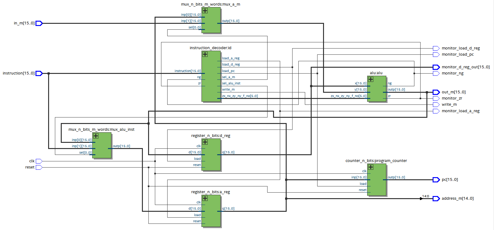
2.6 CPUにまとめる
これまでに作ったモジュール同士を配線してCPUを作る。
コードを見る/隠す
library ieee;
use ieee.std_logic_1164.all;
use ieee.numeric_std.all;

entity cpu is
    generic (
        NUM_BITS: positive := 16
    );
    port (
        clk: in std_logic;
        reset: in std_logic;

        instruction: in std_logic_vector(NUM_BITS-1 downto 0);
        in_m: in std_logic_vector(NUM_BITS-1 downto 0);

        out_m: out std_logic_vector(NUM_BITS-1 downto 0);
        address_m: out std_logic_vector(NUM_BITS-2 downto 0);
        write_m: out std_logic;

        pc: out std_logic_vector(NUM_BITS-1 downto 0);

        monitor_load_a_reg: out std_logic;
        monitor_load_d_reg: out std_logic;
        monitor_load_pc: out std_logic;
        monitor_zr: out std_logic;
        monitor_ng: out std_logic;
        monitor_d_reg_out: out std_logic_vector(NUM_BITS-1 downto 0)
    );
end entity;

architecture rtl of cpu is
    signal alu_out: std_logic_vector(NUM_BITS-1 downto 0);
    signal a_reg_in: std_logic_vector(NUM_BITS-1 downto 0);
    signal a_reg_out: std_logic_vector(NUM_BITS-1 downto 0);
    signal alu_x: std_logic_vector(NUM_BITS-1 downto 0);
    signal alu_y: std_logic_vector(NUM_BITS-1 downto 0);

    signal zx_nx_zy_ny_f_no: std_logic_vector(5 downto 0);
    signal zr: std_logic;
    signal ng: std_logic;

    signal sel_alu_inst: std_logic;
    signal sel_a_m: std_logic;

    signal load_a_reg: std_logic;
    signal load_d_reg: std_logic;
    signal load_pc: std_logic;
begin
    address_m <= a_reg_out(NUM_BITS-2 downto 0);
    out_m <= alu_out;

    monitor_load_a_reg <= load_a_reg;
    monitor_load_d_reg <= load_d_reg;
    monitor_load_pc <= load_pc;
    monitor_zr <= zr;
    monitor_ng <= ng;
    monitor_d_reg_out <= alu_x;

    mux_alu_inst: entity work.mux_n_bits_m_words
    generic map (
        NUM_BITS => NUM_BITS,
        NUM_WORDS => 2
    )
    port map (
        inp(0) => alu_out,
        inp(1) => instruction,
        sel(0) => sel_alu_inst,
        outp => a_reg_in
    );

    a_reg: entity work.register_n_bits
    generic map (
        NUM_BITS => NUM_BITS
    )
    port map (
        clk => clk,
        reset => reset,
        load => load_a_reg,
        d => a_reg_in,
        q => a_reg_out
    );

    d_reg: entity work.register_n_bits
    generic map (
        NUM_BITS => NUM_BITS
    )
    port map (
        clk => clk,
        reset => reset,
        load => load_d_reg,
        d => alu_out,
        q => alu_x
    );

    mux_a_m: entity work.mux_n_bits_m_words
    generic map (
        NUM_BITS => NUM_BITS,
        NUM_WORDS => 2
    )
    port map (
        inp(0) => a_reg_out,
        inp(1) => in_m,
        sel(0) => sel_a_m,
        outp => alu_y
    );

    alu: entity work.alu
    generic map (
        NUM_BITS => NUM_BITS
    )
    port map (
        x => alu_x,
        y => alu_y,

        zx_nx_zy_ny_f_no => zx_nx_zy_ny_f_no,
        zr => zr,
        ng => ng,

        outp => alu_out
    );

    id: entity work.instruction_decoder
    generic map (
        NUM_BITS => 16
    )
    port map (
        instruction => instruction,
        zr => zr,
        ng => ng,
        zx_nx_zy_ny_f_no => zx_nx_zy_ny_f_no,

        load_a_reg => load_a_reg,
        load_d_reg => load_d_reg,
        load_pc => load_pc,
        write_m => write_m,

        sel_alu_inst => sel_alu_inst,
        sel_a_m => sel_a_m
    );

    program_counter: entity work.counter_n_bits
    generic map (
        NUM_BITS => NUM_BITS
    )
    port map (
        inp => a_reg_out,
        clk => clk,
        reset => reset,
        load => load_pc,
        outp => pc
    );

end architecture;
3. ROMを作る
ロジックエレメントは消費せずにMAX10のメモリーブロックに作り込む。Quartus PrimeのIPカタログのROM: 1-PORTを使って自動生成する。テキストは16ビット × 32,768ワードのROM32Kモジュールを作っているが、今使っているMAX10では容量が足りないため、ひとまず16ビット × 4,096ワードのrom4kとしておく。
コードを見る/隠す
LIBRARY ieee;
USE ieee.std_logic_1164.all;

LIBRARY altera_mf;
USE altera_mf.altera_mf_components.all;

ENTITY rom4k IS
	PORT
	(
		address		: IN STD_LOGIC_VECTOR (11 DOWNTO 0);
		clock		: IN STD_LOGIC  := '1';
		q		: OUT STD_LOGIC_VECTOR (15 DOWNTO 0)
	);
END rom4k;


ARCHITECTURE SYN OF rom4k IS

	SIGNAL sub_wire0	: STD_LOGIC_VECTOR (15 DOWNTO 0);

BEGIN
	q    <= sub_wire0(15 DOWNTO 0);

	altsyncram_component : altsyncram
	GENERIC MAP (
		address_aclr_a => "NONE",
		clock_enable_input_a => "BYPASS",
		clock_enable_output_a => "BYPASS",
		init_file => "rom_init.mif",
		intended_device_family => "MAX 10",
		lpm_hint => "ENABLE_RUNTIME_MOD=NO",
		lpm_type => "altsyncram",
		numwords_a => 4096,
		operation_mode => "ROM",
		outdata_aclr_a => "NONE",
		outdata_reg_a => "UNREGISTERED",
		widthad_a => 12,
		width_a => 16,
		width_byteena_a => 1
	)
	PORT MAP (
		address_a => address,
		clock0 => clock,
		q_a => sub_wire0
	);


END SYN;
4. メモリーを作る
メモリーマップは下のとおりとする。
ram: 0~8191番地
screen: 8192~8575番地
keyboard: 8576番地
out_reg: 8577番地
4.1 ramモジュールを作る
ROMと同じくMAX10のメモリーブロックに作り込む。ひとまず16ビット × 8192ワードのram8kとしておく。IPカタログのRAM: 1-PORTを使って自動生成する。
コードを見る/隠す
LIBRARY ieee;
USE ieee.std_logic_1164.all;

LIBRARY altera_mf;
USE altera_mf.altera_mf_components.all;

ENTITY ram8k IS
	PORT
	(
		aclr		: IN STD_LOGIC  := '0';
		address		: IN STD_LOGIC_VECTOR (12 DOWNTO 0);
		clock		: IN STD_LOGIC  := '1';
		data		: IN STD_LOGIC_VECTOR (15 DOWNTO 0);
		wren		: IN STD_LOGIC ;
		q		: OUT STD_LOGIC_VECTOR (15 DOWNTO 0)
	);
END ram8k;


ARCHITECTURE SYN OF ram8k IS

	SIGNAL sub_wire0	: STD_LOGIC_VECTOR (15 DOWNTO 0);

BEGIN
	q    <= sub_wire0(15 DOWNTO 0);

	altsyncram_component : altsyncram
	GENERIC MAP (
		clock_enable_input_a => "BYPASS",
		clock_enable_output_a => "BYPASS",
		intended_device_family => "MAX 10",
		lpm_hint => "ENABLE_RUNTIME_MOD=NO",
		lpm_type => "altsyncram",
		numwords_a => 8192,
		operation_mode => "SINGLE_PORT",
		outdata_aclr_a => "CLEAR0",
		outdata_reg_a => "UNREGISTERED",
		power_up_uninitialized => "FALSE",
		read_during_write_mode_port_a => "NEW_DATA_NO_NBE_READ",
		widthad_a => 13,
		width_a => 16,
		width_byteena_a => 1
	)
	PORT MAP (
		aclr0 => aclr,
		address_a => address,
		clock0 => clock,
		data_a => data,
		wren_a => wren,
		q_a => sub_wire0
	);


END SYN;
4.2 screenモジュールを作る
これもMAX10のメモリーブロックに作り込む。ひとまず16ビット × 384ワードのscreen384としておく。IPカタログのRAM: 2-PORTを使って自動生成する。書き込みアドレスと読み込みアドレスとを分けた。
コードを見る/隠す
LIBRARY ieee;
USE ieee.std_logic_1164.all;

LIBRARY altera_mf;
USE altera_mf.altera_mf_components.all;

ENTITY screen384 IS
	PORT
	(
		aclr		: IN STD_LOGIC  := '0';
		clock		: IN STD_LOGIC  := '1';
		data		: IN STD_LOGIC_VECTOR (15 DOWNTO 0);
		rdaddress		: IN STD_LOGIC_VECTOR (8 DOWNTO 0);
		wraddress		: IN STD_LOGIC_VECTOR (8 DOWNTO 0);
		wren		: IN STD_LOGIC  := '0';
		q		: OUT STD_LOGIC_VECTOR (15 DOWNTO 0)
	);
END screen384;


ARCHITECTURE SYN OF screen384 IS

	SIGNAL sub_wire0	: STD_LOGIC_VECTOR (15 DOWNTO 0);

BEGIN
	q    <= sub_wire0(15 DOWNTO 0);

	altsyncram_component : altsyncram
	GENERIC MAP (
		address_aclr_b => "CLEAR0",
		address_reg_b => "CLOCK0",
		clock_enable_input_a => "BYPASS",
		clock_enable_input_b => "BYPASS",
		clock_enable_output_b => "BYPASS",
		intended_device_family => "MAX 10",
		lpm_type => "altsyncram",
		numwords_a => 384,
		numwords_b => 384,
		operation_mode => "DUAL_PORT",
		outdata_aclr_b => "CLEAR0",
		outdata_reg_b => "UNREGISTERED",
		power_up_uninitialized => "FALSE",
		read_during_write_mode_mixed_ports => "DONT_CARE",
		widthad_a => 9,
		widthad_b => 9,
		width_a => 16,
		width_b => 16,
		width_byteena_a => 1
	)
	PORT MAP (
		aclr0 => aclr,
		address_a => wraddress,
		address_b => rdaddress,
		clock0 => clock,
		data_a => data,
		wren_a => wren,
		q_b => sub_wire0
	);


END SYN;
4.3 keyboardモジュールとout_regモジュールとを作る
テキストにはないが、確認用として直接外部へ何かを出力できるよう、RAMとは別に専用のアウトレジスタout_regを設けてアドレスをマップしておく。前にAレジスタ用およびDレジスタ用に作った16ビットレジスタを使う。keyboardモジュールも同様。
4.4 メモリーコントローラーを作る
アドレスに応じてram8k、screen384、out_reg、keyboardの各ramのwrite enable信号を生成する。またscreen384へ与える書き込みアドレスは、スクリーンのベースアドレスのぶんだけオフセットする。
コードを見る/隠す
library ieee;
use ieee.std_logic_1164.all;
use ieee.numeric_std.all;

entity memory_controller is
    generic (
        NUM_BITS: positive := 16;

        SCREEN_WORDS: positive := 384;
        SCREEN_SEL_BITS: positive := 9;

        SCREEN_BASE_ADDRESS: natural := 8192;
        KEYBOARD_ADDRESS: natural := 8192 + 384;
        OUT_REG_ADDRESS: natural := 8192 + 384 + 1
    );
    port (
        address: in std_logic_vector(NUM_BITS-2 downto 0);
        load: in std_logic;

        from_ram: in std_logic_vector(NUM_BITS-1 downto 0);
        from_keyboard: in std_logic_vector(NUM_BITS-1 downto 0);
        to_cpu: out std_logic_vector(NUM_BITS-1 downto 0);

        screen_write_address: out std_logic_vector(SCREEN_SEL_BITS-1 downto 0);

        write_ram: out std_logic;
        write_screen: out std_logic;
        write_out_reg: out std_logic
    );
end entity;

architecture rtl of memory_controller is
    signal us_address: unsigned(address'range);
begin
    us_address <= unsigned(address);

    -- screen384へ与えるアドレスは、SCREEN_BASE_ADDRESSの分だけオフセットする。
    screen_write_address <=
        std_logic_vector(us_address - SCREEN_BASE_ADDRESS)(screen_write_address'range);

    write_ram <= '1'
        when
            load = '1' and
            us_address < SCREEN_BASE_ADDRESS
        else '0';
    write_screen <= '1'
        when
            load = '1' and
            SCREEN_BASE_ADDRESS <= us_address and
            us_address < KEYBOARD_ADDRESS
        else '0';
    write_out_reg <= '1'
        when
            load = '1' and
            us_address = OUT_REG_ADDRESS
        else '0';
    to_cpu <=
        from_ram when us_address < SCREEN_BASE_ADDRESS else
        from_keyboard when us_address = KEYBOARD_ADDRESS else
        (others => '-');

end architecture;
4.5 メモリーにまとめる
これまでに作った各モジュールをメモリーにまとめる。
コードを見る/隠す
library ieee;
use ieee.std_logic_1164.all;
use ieee.numeric_std.all;
use ieee.math_real.all;

package memory_pkg is
    function num_sel_bits(num_words: positive) return positive;
end package;
package body memory_pkg is
    function num_sel_bits(num_words: natural) return positive is
    begin
        return integer(ceil(log2(real(num_words))));
    end function;
end package body;
use work.memory_pkg.all;
--------------------------------------------------------------------
library ieee;
use ieee.std_logic_1164.all;
use ieee.numeric_std.all;

entity memory is
    generic (
        NUM_BITS: positive := 16;

        RAM_WORDS: natural := 8192;
        SCREEN_WORDS: natural := 384;
        SCREEN_SEL_BITS: natural := 9;

        SCREEN_BASE_ADDRESS: natural := 8192;
        KEYBOARD_ADDRESS: natural := 8192 + 384;
        OUT_REG_ADDRESS: natural := 8192 + 384 + 1
    );
    port (
        inp: in std_logic_vector(NUM_BITS-1 downto 0);
        clk: in std_logic;
        reset: in std_logic;
        address: in std_logic_vector(NUM_BITS-2 downto 0);
        load: in std_logic;
        keyboard_in: in std_logic_vector(NUM_BITS-1 downto 0);

        outp: out std_logic_vector(NUM_BITS-1 downto 0);

        screen_sel: in std_logic_vector(SCREEN_SEL_BITS-1 downto 0);
        screen_out: out std_logic_vector(NUM_BITS-1 downto 0);

        out_reg_out: out std_logic_vector(NUM_BITS-1 downto 0)
    );
end entity;

architecture rtl of memory is
    signal write_ram: std_logic;
    signal write_screen: std_logic;
    signal write_out_reg: std_logic;

    signal ram_out: std_logic_vector(NUM_BITS-1 downto 0);
    signal keyboard_out: std_logic_vector(NUM_BITS-1 downto 0);

    signal wraddress_offsetted: std_logic_vector(SCREEN_SEL_BITS-1 downto 0);
begin
    -------------------------------------------------------
    gen_ram: case RAM_WORDS generate
        when 8192 =>
            ram_module: entity work.ram8k
            port map (
                aclr => reset,
                address => address(num_sel_bits(RAM_WORDS)-1 downto 0),
                clock => clk,
                data => inp,
                wren => write_ram,
                q => ram_out
            );
        when 4096 =>
            ram_module: entity work.ram4k
            port map (
                aclr => reset,
                address => address(num_sel_bits(RAM_WORDS)-1 downto 0),
                clock => clk,
                data => inp,
                wren => write_ram,
                q => ram_out
            );
        when others =>
            ram_module: entity work.ram8k
            port map (
                aclr => reset,
                address => address(num_sel_bits(RAM_WORDS)-1 downto 0),
                clock => clk,
                data => inp,
                wren => write_ram,
                q => ram_out
            );
    end generate;
    -------------------------------------------------------


    -- IPカタログのRAM: 2-PORTを使って作った。
    -- readアドレスとwriteアドレスと分けた。
    screen_module: entity work.screen384
    port map (
        aclr => reset,
		clock => clk,
		data => inp,
		rdaddress => screen_sel,
		wraddress => wraddress_offsetted,
		wren => write_screen,
		q => screen_out
    );

    keyboard_module: entity work.register_n_bits
    generic map (
        NUM_BITS => NUM_BITS
    )
    port map (
        clk => clk,
        reset => reset,
        load => '1',
        d => keyboard_in,
        q => keyboard_out
    );

    out_reg_module: entity work.register_n_bits
    generic map (
        NUM_BITS => NUM_BITS
    )
    port map (
        clk => clk,
        reset => reset,
        load => write_out_reg,
        d => inp,
        q => out_reg_out
    );

    mem_cnt: entity work.memory_controller
    generic map (
        NUM_BITS => NUM_BITS,

        SCREEN_WORDS => SCREEN_WORDS,
        SCREEN_SEL_BITS => SCREEN_SEL_BITS,

        SCREEN_BASE_ADDRESS => SCREEN_BASE_ADDRESS,
        KEYBOARD_ADDRESS => KEYBOARD_ADDRESS,
        OUT_REG_ADDRESS => OUT_REG_ADDRESS
    )
    port map (
        address => address,
        load => load,

        from_ram => ram_out,
        from_keyboard => keyboard_out,
        to_cpu => outp,

        screen_write_address => wraddress_offsetted,

        write_ram => write_ram,
        write_screen => write_screen,
        write_out_reg => write_out_reg
    );

end architecture;
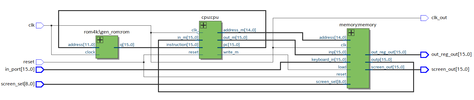
5. Hackコンピューターを作る
いよいよ、これまで作ってきたモジュール同士を配線してHackコンピューターを作る。
コードを見る/隠す
library ieee;
use ieee.std_logic_1164.all;
use ieee.numeric_std.all;
use ieee.math_real.all;

package hack_pkg is
    function num_sel_bits(num_words: positive) return positive;

    constant NUM_BITS_CONST: positive := 16;
    constant ROM_WORDS_CONST: positive := 4096;
    constant RAM_WORDS_CONST: positive := 8192;
    constant SCREEN_BASE_CONST: natural := RAM_WORDS_CONST + 0;
    constant SCREEN_WORDS_CONST: natural := 384;
    constant KEYBOARD_ADDRESS_CONST: natural := RAM_WORDS_CONST + SCREEN_WORDS_CONST;
    constant OUT_REG_ADDRESS_CONST: natural := KEYBOARD_ADDRESS_CONST + 1;
end package;

package body hack_pkg is
    function num_sel_bits(num_words: natural) return positive is
    begin
        return integer(ceil(log2(real(num_words))));
    end function;
end package body;
use work.hack_pkg.all;
--------------------------------------------------------------------
library ieee;
use ieee.std_logic_1164.all;
use ieee.numeric_std.all;

entity hack is
    generic (
        NUM_BITS: positive := NUM_BITS_CONST;
        ROM_WORDS: positive := ROM_WORDS_CONST;

        RAM_WORDS: positive := RAM_WORDS_CONST;
        SCREEN_WORDS: positive := SCREEN_WORDS_CONST;

        SCREEN_BASE_ADDRESS: natural := SCREEN_BASE_CONST;
        KEYBOARD_ADDRESS: natural := KEYBOARD_ADDRESS_CONST;
        OUT_REG_ADDRESS: natural := OUT_REG_ADDRESS_CONST
    );
    port (
        --monitor_load_a_reg: out std_logic;
        --monitor_load_d_reg: out std_logic;
        --monitor_load_pc: out std_logic;
        --monitor_zr: out std_logic;
        --monitor_ng: out std_logic;
        --monitor_d_reg_out: out std_logic_vector(NUM_BITS-1 downto 0)

        reset: in std_logic;
        clk: in std_logic;
        in_port: in std_logic_vector(NUM_BITS-1 downto 0);

        clk_out: out std_logic;

        screen_sel: in std_logic_vector(num_sel_bits(SCREEN_WORDS)-1 downto 0);
        screen_out: out std_logic_vector(NUM_BITS-1 downto 0);

        out_reg_out: out std_logic_vector(NUM_BITS-1 downto 0)
    );
end entity;

architecture rtl of hack is
    signal in_m: std_logic_vector(in_port'range);
    signal instruction: std_logic_vector(in_port'range);
    signal write_m: std_logic;
    signal out_m: std_logic_vector(in_port'range);
    signal address_m: std_logic_vector(NUM_BITS-2 downto 0);
    signal out_pc: std_logic_vector(in_port'range);
begin
    clk_out <= clk;

    cpu: entity work.cpu
    port map (
        clk => not clk,
        reset => reset,
        instruction => instruction,
        in_m => in_m,
        out_m => out_m,
        address_m => address_m,
        write_m => write_m,
        pc => out_pc/*,

        monitor_load_a_reg => monitor_load_a_reg,
        monitor_load_d_reg => monitor_load_d_reg,
        monitor_load_pc => monitor_load_pc,
        monitor_zr => monitor_zr
        monitor_ng => monitor_ng,
        monitor_d_reg_out => monitor_d_reg_out
        */
    );

    memory: entity work.memory
    generic map (
        NUM_BITS => NUM_BITS,

        RAM_WORDS => RAM_WORDS,
        SCREEN_WORDS => SCREEN_WORDS,

        SCREEN_BASE_ADDRESS => SCREEN_BASE_ADDRESS,
        KEYBOARD_ADDRESS => KEYBOARD_ADDRESS,
        OUT_REG_ADDRESS => OUT_REG_ADDRESS
    )
    port map (
        inp => out_m,
        clk => clk,
        reset => reset,
        address => address_m,
        load => write_m,
        outp => in_m,

        screen_sel => screen_sel,
        screen_out => screen_out,

        keyboard_in => in_port,

        out_reg_out => out_reg_out
    );


    -----------------------------------------------------------
    gen_rom: case ROM_WORDS generate
        when 4096 =>
            rom: entity work.rom4k
            port map (
                address => out_pc(num_sel_bits(ROM_WORDS)-1 downto 0),
                clock => clk,
                q => instruction
            );
        when 8192 =>
            rom: entity work.rom8k
            port map (
                address => out_pc(num_sel_bits(ROM_WORDS)-1 downto 0),
                clock => clk,
                q => instruction
            );
        when 16384 =>
            rom: entity work.rom16k
            port map (
                address => out_pc(num_sel_bits(ROM_WORDS)-1 downto 0),
                clock => clk,
                q => instruction
            );
        when others =>
            rom: entity work.rom4k
            port map (
                address => out_pc(num_sel_bits(ROM_WORDS)-1 downto 0),
                clock => clk,
                q => instruction
            );
    end generate;
    -----------------------------------------------------------


end architecture;
6. 動作確認をする
0d1から0d361までの総和を求める。0d65341 (0b1111 1111 0011 1101)になれば正解。
テストした.asmファイルを見る/隠す
////////////////////////////////////
// 1からRAM[0]までの総和を求める。//
////////////////////////////////////

// ディップスイッチで設定した任意の値をRAM[0]に格納する。
@KBD
D=M
@R0
M=D

// 加算する値の初期値i=1
@i
M=1

// 総和の初期値sum=0
@sum
M=0

(LOOP)
@i
D=M

// 途中の何かをOUT_PORTに出力する。
@OUT_PORT
M=D

@R0
D=D-M

// 途中の何かをOUT_PORTに出力する。
@OUT_PORT
M=D

// if i-RAM[0] > 0: goto (STOP)
// すなわち計算し終わったらループを抜けて(STOP)へ飛ぶ。
@STOP
D;JGT

// sum+=i
@sum
D=M

// 途中の何かをOUT_PORTに出力する。
@OUT_PORT
M=D

@i
D=D+M

// 途中の何かをOUT_PORTに出力する。
@OUT_PORT
M=D

@sum
M=D

// i++
@i
M=M+1
@LOOP
0;JMP

(STOP)
// R1=sum
@sum
D=M

// 最終結果をOUT_PORTに出力する。
@OUT_PORT
M=D

(END)
@END
0;JMP
テストした.mifファイル(romの初期化ファイル)を見る/隠す
WIDTH=16;
DEPTH=4096;
ADDRESS_RADIX=UNS;
DATA_RADIX=BIN;
CONTENT BEGIN

    0 :0010000110000000;
    1 :1111110000010000;
    2 :0000000000000000;
    3 :1110001100001000;
    4 :0000000000010000;
    5 :1110111111001000;
    6 :0000000000010001;
    7 :1110101010001000;
    8 :0000000000010000;
    9 :1111110000010000;
   10 :0010000110000001;
   11 :1110001100001000;
   12 :0000000000000000;
   13 :1111010011010000;
   14 :0010000110000001;
   15 :1110001100001000;
   16 :0000000000100000;
   17 :1110001100000001;
   18 :0000000000010001;
   19 :1111110000010000;
   20 :0010000110000001;
   21 :1110001100001000;
   22 :0000000000010000;
   23 :1111000010010000;
   24 :0010000110000001;
   25 :1110001100001000;
   26 :0000000000010001;
   27 :1110001100001000;
   28 :0000000000010000;
   29 :1111110111001000;
   30 :0000000000001000;
   31 :1110101010000111;
   32 :0000000000010001;
   33 :1111110000010000;
   34 :0010000110000001;
   35 :1110001100001000;
   36 :0000000000100100;
   37 :1110101010000111;

END;
6.1 実行結果
クロックは1 kHzにした。
7. ファイル一式
8. アセンブラ篇へ続く