前回からの続きです。
- 第1回:BGP Route Serverを用いたWANネットワーク設計
- 第2回:BGP Route ServerによるWAN経路の一元管理 ← 今回はココ
BGP Route ServerによるWAN経路の一元管理
BGP Route Serverは他のすべてのルータとピアリングしているため、制限はあるものの経路制御に介在することができます。
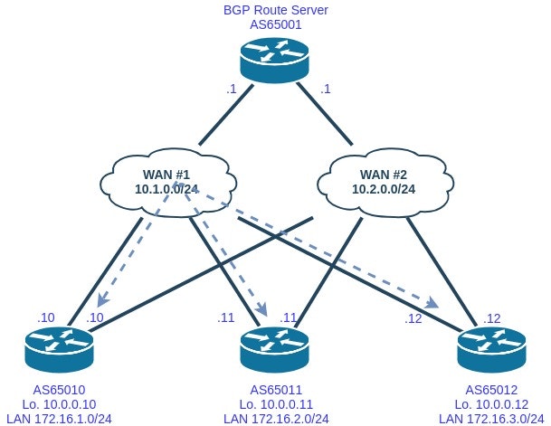
ネットワーク構成
前回のおさらいになりますが、WANの通信経路は以下の通り、WAN1を常時利用しています。
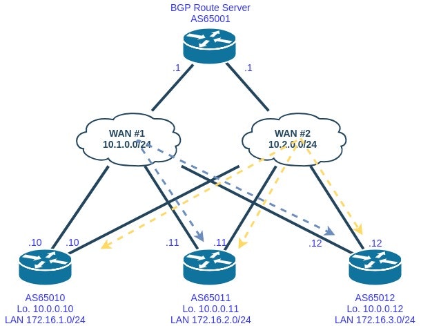
例えば作業やメンテナンス等で、AS65010でWAN#1の経路を利用させなくないケースがあったとします。そのような場合、あらかじめ通信を止めずに次のような経路に変更できるのが理想的です。
この作業であれば、BGP Route Serverの設定変更のみで通信の迂回が可能です。具体的にはBGP Route ServerからAS65010にWAN#1経由で経路配信する際、すべての経路情報にMED:100を付与し、BGP Route ServerからAS65011, AS65012にWAN#1経由で経路配信する際、AS65010から受信した経路情報にMED:100を付与します。元のコンフィグを活用した設定となるので、まずは元のコンフィグから見ていきます。
router bgp 65001
 route-server-context WAN1_CONTEXT
  !
  address-family ipv4 unicast
   import-map WAN1_IM
  exit-address-family
 exit-route-server-context
 !
 route-server-context WAN2_CONTEXT
  !
  address-family ipv4 unicast
   import-map WAN2_IM
  exit-address-family
 exit-route-server-context
 !
 bgp router-id 10.0.0.1
 bgp always-compare-med
 bgp log-neighbor-changes
 timers bgp 3 20
 neighbor 10.1.0.10 remote-as 65010
 neighbor 10.1.0.11 remote-as 65011
 neighbor 10.1.0.12 remote-as 65012
 neighbor 10.2.0.10 remote-as 65010
 neighbor 10.2.0.11 remote-as 65011
 neighbor 10.2.0.12 remote-as 65012

 address-family ipv4
  neighbor 10.1.0.10 activate
  neighbor 10.1.0.10 send-community
  neighbor 10.1.0.10 route-server-client context WAN1_CONTEXT
  neighbor 10.1.0.10 route-map LOW_PRIORITY out
  neighbor 10.1.0.11 activate
  neighbor 10.1.0.11 send-community
  neighbor 10.1.0.11 route-server-client context WAN1_CONTEXT
  neighbor 10.1.0.11 route-map WAN1_OUT out
  neighbor 10.1.0.12 activate
  neighbor 10.1.0.12 send-community
  neighbor 10.1.0.12 route-server-client context WAN1_CONTEXT
  neighbor 10.1.0.12 route-map WAN1_OUT out
  neighbor 10.2.0.10 activate
  neighbor 10.2.0.10 send-community
  neighbor 10.2.0.10 route-server-client context WAN2_CONTEXT
  neighbor 10.2.0.10 route-map WAN2_OUT out
  neighbor 10.2.0.11 activate
  neighbor 10.2.0.11 send-community
  neighbor 10.2.0.11 route-server-client context WAN2_CONTEXT
  neighbor 10.2.0.11 route-map WAN2_OUT out
  neighbor 10.2.0.12 activate
  neighbor 10.2.0.12 send-community
  neighbor 10.2.0.12 route-server-client context WAN2_CONTEXT
  neighbor 10.2.0.12 route-map WAN2_OUT out
 exit-address-family
!
ip forward-protocol nd
no ip http server
no ip http secure-server
!
ip bgp-community new-format
ip community-list 1 permit 65001:1
ip community-list 2 permit 65001:2

route-map WAN2_IM permit 10
 match community 2

route-map WAN1_IM permit 10
 match community 1

route-map WAN1_OUT permit 100
 set community none

route-map WAN2_OUT permit 100
 set community none
WAN#1向けのピアには、WAN1_OUTというroute-mapが定義されていますが、AS65010向けには別のroute-mapを適用し、AS65011, 65012向けはWAN1_OUTのroute-mapをそのまま有効活用します。追加するコンフィグは以下のとおりです。
route-map LOW_PRIORITY permit 10
 set metric 100
 set community none

ip as-path access-list 1 permit ^65010$

route-map WAN1_OUT permit 10
 match as-path 1
 set metric 100
 set community none

router bgp 65001
 address-family ipv4 unicast
  neighbor 10.1.0.10 route-map LOW_PRIORITY out
end

clear ip bgp * soft
これでAS65010の経路が切り替わります。AS65010からBGPテーブル、ルーティングテーブルを確認します。
R65010>sh ip bgp
BGP table version is 197, local router ID is 10.0.0.10
Status codes: s suppressed, d damped, h history, * valid, > best, i - internal,
              r RIB-failure, S Stale
Origin codes: i - IGP, e - EGP, ? - incomplete

   Network          Next Hop            Metric LocPrf Weight Path
*> 10.0.0.10/32     0.0.0.0                  0         32768 i
*  10.0.0.11/32     10.1.0.11              100             0 65011 i
*>                  10.2.0.11               20             0 65011 i
*  10.0.0.12/32     10.1.0.12              100             0 65012 i
*>                  10.2.0.12               20             0 65012 i
r  10.1.0.0/24      10.1.0.12              100             0 65012 i
r>                  10.2.0.12               20             0 65012 i
r  10.2.0.0/24      10.1.0.12              100             0 65012 i
r>                  10.2.0.12               20             0 65012 i
*> 172.16.1.0/24    0.0.0.0                  0         32768 i
*  172.16.2.0/24    10.1.0.11              100             0 65011 i
*>                  10.2.0.11               20             0 65011 i
*  172.16.3.0/24    10.1.0.12              100             0 65012 i
*>                  10.2.0.12               20             0 65012 i
R65010>sh ip route
Codes: C - connected, S - static, R - RIP, M - mobile, B - BGP
       D - EIGRP, EX - EIGRP external, O - OSPF, IA - OSPF inter area
       N1 - OSPF NSSA external type 1, N2 - OSPF NSSA external type 2
       E1 - OSPF external type 1, E2 - OSPF external type 2
       i - IS-IS, su - IS-IS summary, L1 - IS-IS level-1, L2 - IS-IS level-2
       ia - IS-IS inter area, * - candidate default, U - per-user static route
       o - ODR, P - periodic downloaded static route

Gateway of last resort is not set

     172.16.0.0/24 is subnetted, 3 subnets
C       172.16.1.0 is directly connected, Loopback1
B       172.16.2.0 [20/20] via 10.2.0.11, 02:48:17
B       172.16.3.0 [20/20] via 10.2.0.12, 02:48:17
     10.0.0.0/8 is variably subnetted, 5 subnets, 2 masks
C       10.0.0.10/32 is directly connected, Loopback0
B       10.0.0.11/32 [20/20] via 10.2.0.11, 02:48:17
B       10.0.0.12/32 [20/20] via 10.2.0.12, 02:48:17
C       10.2.0.0/24 is directly connected, FastEthernet1
C       10.1.0.0/24 is directly connected, FastEthernet0
BGPテーブルからWAN#1経由の経路情報にMED:100が付与され、ルーティングテーブルから他ASへのNextHopがWAN#2経由(10.2.0.xx)になっていることがわかります。
AS65011のBGPテーブル、ルーティングテーブルは以下のとおりです。
ubnt@ubnt2:~$ show ip bgp
BGP table version is 0, local router ID is 10.0.0.11
Status codes: s suppressed, d damped, h history, * valid, > best, i - internal,
              r RIB-failure, S Stale, R Removed
Origin codes: i - IGP, e - EGP, ? - incomplete

   Network          Next Hop            Metric LocPrf Weight Path
*  10.0.0.10/32     10.1.0.10              100             0 65010 i
*>                  10.2.0.10               20             0 65010 i
*> 10.0.0.11/32     0.0.0.0                  1         32768 i
*  10.0.0.12/32     10.2.0.12               20             0 65012 i
*>                  10.1.0.12               10             0 65012 i
*  10.1.0.0/24      10.2.0.12               20             0 65012 i
*>                  10.1.0.12               10             0 65012 i
*  10.2.0.0/24      10.2.0.12               20             0 65012 i
*>                  10.1.0.12               10             0 65012 i
*  172.16.1.0/24    10.1.0.10              100             0 65010 i
*>                  10.2.0.10               20             0 65010 i
*> 172.16.2.0/24    0.0.0.0                  1         32768 i
*  172.16.3.0/24    10.2.0.12               20             0 65012 i
*>                  10.1.0.12               10             0 65012 i

Total number of prefixes 8
ubnt@ubnt2:~$ show ip route
Codes: K - kernel route, C - connected, S - static, R - RIP, O - OSPF,
       I - ISIS, B - BGP, > - selected route, * - FIB route

B>* 10.0.0.10/32 [20/20] via 10.2.0.10, eth2, 02:45:10
C>* 10.0.0.11/32 is directly connected, lo
B>* 10.0.0.12/32 [20/10] via 10.1.0.12, eth1, 02:51:23
B   10.1.0.0/24 [20/10] via 10.1.0.12 inactive, 02:51:23
C>* 10.1.0.0/24 is directly connected, eth1
B   10.2.0.0/24 [20/10] via 10.1.0.12, 02:51:23
C>* 10.2.0.0/24 is directly connected, eth2
C>* 127.0.0.0/8 is directly connected, lo
B>* 172.16.1.0/24 [20/20] via 10.2.0.10, eth2, 02:45:10
C>* 172.16.2.0/24 is directly connected, eth3
B>* 172.16.3.0/24 [20/10] via 10.1.0.12, eth1, 02:51:23
C>* 192.168.1.0/24 is directly connected, eth0
AS65010へのNextHopはWAN#2経由(10.2.0.xx)で、AS65012へのNextHopはWAN#1経由(10.1.0.xx)になっていることがわかります。
最後に、AS65012のBGPテーブル、ルーティングテーブルも見ていきます。
root@R65012> show route receive-protocol bgp 10.1.0.1

inet.0: 11 destinations, 15 routes (11 active, 0 holddown, 0 hidden)
  Prefix                  Nexthop              MED     Lclpref    AS path
  10.0.0.10/32            10.1.0.10            100                65010 I
* 10.0.0.11/32            10.1.0.11            10                 65011 I
  172.16.1.0/24           10.1.0.10            100                65010 I
* 172.16.2.0/24           10.1.0.11            10                 65011 I

root@R65012> show route receive-protocol bgp 10.2.0.1

inet.0: 11 destinations, 15 routes (11 active, 0 holddown, 0 hidden)
  Prefix                  Nexthop              MED     Lclpref    AS path
* 10.0.0.10/32            10.2.0.10            20                 65010 I
  10.0.0.11/32            10.2.0.11            20                 65011 I
* 172.16.1.0/24           10.2.0.10            20                 65010 I
  172.16.2.0/24           10.2.0.11            20                 65011 I

root@R65012> show route

inet.0: 11 destinations, 15 routes (11 active, 0 holddown, 0 hidden)
+ = Active Route, - = Last Active, * = Both

10.0.0.10/32       *[BGP/170] 1w0d 02:07:30, MED 20, localpref 100, from 10.2.0.1
                      AS path: 65010 I
                    > to 10.2.0.10 via fe-0/0/3.0
                    [BGP/170] 1w0d 02:07:30, MED 100, localpref 100, from 10.1.0.1
                      AS path: 65010 I
                    > to 10.1.0.10 via fe-0/0/2.0
10.0.0.11/32       *[BGP/170] 1w0d 02:13:43, MED 10, localpref 100, from 10.1.0.1
                      AS path: 65011 I
                    > to 10.1.0.11 via fe-0/0/2.0
                    [BGP/170] 1w0d 02:13:43, MED 20, localpref 100, from 10.2.0.1
                      AS path: 65011 I
                    > to 10.2.0.11 via fe-0/0/3.0
10.0.0.12/32       *[Direct/0] 1w0d 10:27:12
                    > via lo0.0
10.1.0.0/24        *[Direct/0] 1w0d 10:06:44
                    > via fe-0/0/2.0
10.1.0.12/32       *[Local/0] 1w0d 10:47:20
                      Local via fe-0/0/2.0
10.2.0.0/24        *[Direct/0] 1w0d 09:52:01
                    > via fe-0/0/3.0
10.2.0.12/32       *[Local/0] 1w0d 10:47:20
                      Local via fe-0/0/3.0
172.16.1.0/24      *[BGP/170] 1w0d 02:07:30, MED 20, localpref 100, from 10.2.0.1
                      AS path: 65010 I
                    > to 10.2.0.10 via fe-0/0/3.0
                    [BGP/170] 1w0d 02:07:30, MED 100, localpref 100, from 10.1.0.1
                      AS path: 65010 I
                    > to 10.1.0.10 via fe-0/0/2.0
172.16.2.0/24      *[BGP/170] 1w0d 02:13:43, MED 10, localpref 100, from 10.1.0.1
                      AS path: 65011 I
                    > to 10.1.0.11 via fe-0/0/2.0
                    [BGP/170] 1w0d 02:13:43, MED 20, localpref 100, from 10.2.0.1
                      AS path: 65011 I
                    > to 10.2.0.11 via fe-0/0/3.0
172.16.3.0/24      *[Direct/0] 1w0d 09:30:08
                    > via fe-0/0/1.0
172.16.3.1/32      *[Local/0] 1w0d 09:30:17
                      Local via fe-0/0/1.0
AS65010へのNextHopはWAN#2経由(10.2.0.xx)で、AS65011へのNextHopはWAN#1経由(10.1.0.xx)になっていることがわかります。
このようなかたちで、BGP Route Serverを介して各ASの経路制御を行うことができます。本当はAS-PATHの追加で経路制御を行ったほうがTransit ASが入ってきた時にも柔軟に経路制御できるのでいいのですが、私が試した限りでは、CiscoのBGP Route ServerではAS-PATHの追加ができないようです(MEDとCOMMUNITYアトリビュートは使えます)。AS65010〜65012ではLOCAL_PREFやAS-PATH、MEDを用いてより柔軟な経路制御ができます。
おわりに
今回はBGP Route Serverを用いたWANネットワーク経路制御を見ていきました。この構成だと、BGP Route Serverのみで経路制御できるので、経路制御の自動化が簡単にできます。試せてないですが、ピアのAS-PATHとIPアドレス情報を変数にすれば、Ansibleなどを使ってBGP Route Serverから各ASの経路の切り替えが一発でできるようになると思います。