x 6GPIOは、書き込みが難しいので開発が難航
x 注意あり
目的
カラー液晶のテスト
●結果


回路は、各自にデータシートを確認の事
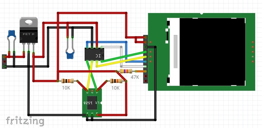
1 RS(DC)
2 VDD
3 GND
4 CS
8 (SWD CLK)(SPI CLK)
7 (SWD DATA)(SPI DATA)
6 I2C
5 I2C
●プログラム
ili9341_SPI_monotone_REG3_031
//ili9341_SPI_monotone_REG3_031


//ヘッダーファイル
#include <Adafruit_GFX.h>
#include "hh.h"
#include <Wire.h>

//定義
#define STTS751 0x39
#define SCREEN_WIDTH  (240-16-16) // OLED display width, in pixels
#define SCREEN_HEIGHT 200 // OLED display height, in pixels
NA_ST7735_P display(SCREEN_WIDTH, SCREEN_HEIGHT);


// ビットマップデータ
uint8_t databytes[8] =

{

  0b01100110,
  0b10101111,
  0b10111111,
  0b11011111,

  0b01111110,
  0b01111110,
  0b00111100,
  0b00011000

};


//初期化
void setup() {

  delay(3000); //do not delete

  // I2Cアドレスは使用するディスプレイに合わせて変更する
  display.begin();

  //i2cの初期化
  Wire.setSDA(PA12);
  Wire.setSCL(PA11);
  Wire.begin(); //pa12 pa11

}//setup


//メインループ
void loop() {

  //温度の読み込み
  char s1[2] = {0,0}; //センサーの値
  char s2[2] = {0,0}; //センサーの値
  int ii=0;

  //0番目のレジスター 温度整数部
  Wire.beginTransmission(STTS751);
  Wire.write(0);
  Wire.endTransmission();
  delay(1);
  //1
  Wire.requestFrom(STTS751, 1);
  s1[0]=99;
  while(Wire.available())  {    // 要求より短いデータが来る可能性あり
    s1[ii++] = (int)Wire.read();       // 1バイトを受信
  }//while
  delay(1);

  //2番目のレジスター 温度小数部
  Wire.beginTransmission(STTS751);
  Wire.write(2);
  Wire.endTransmission();
  delay(1);
  //2
  ii=0;
  Wire.requestFrom(STTS751, 1);
  s2[0]=0xc0;
  while(Wire.available())  {    // 要求より短いデータが来る可能性あり
    s2[ii++] = (int)Wire.read();       // 1バイトを受信
  }//while

  //s1[0]=26;           //debug
  //s1[1]=0x12;         //debug
  //s2[0]=0x00; //0.0   //debug
  //s2[0]=0x40; //0.25  //debug
  //s2[0]=0x80; //0.5   //debug
  //s2[0]=0xc0; //0.75  //debug

  //配列の定義
  char str1[]={'2','6','.','5','0',0};
  char ti1[]={'0','2','5','7'};
  char ti2[]={'0','5','0','5'};

  //変換処理 たぶん難しいのでわかる人に聞いて!!
  //小規模マイコン用のリッチでは、ない処理
  //DIV10は、10の割り算処理
  //ex  (19*204.8)/2048=1.9
  //仮に (19*205  )/2048=1 (小数点以降切り捨て)
  //余りは、10で割って10掛けて引けばいい
  //ex 19/10=1 1*10=10 19-10=9 (小数点以降切り捨て)
  //2進固定小数点は、1/2,1/4,1/8,...となる
  //8ビットを6回シフトして11Bでマスクすると1/2,1/4が
  //取り出せて、表引きしている。
  //情報系の大学で習う大人な処理
#define DIV10(xx) ((xx*205)>>11)
  str1[0]='0'+DIV10(s1[0]);
  if(str1[0]=='0'){str1[0]=' ';}
  str1[1]='0'+s1[0]-(DIV10(s1[0])*10);
  str1[2]='.';
  str1[3]=ti1[(s2[0]>>6)&3];
  str1[4]=ti2[(s2[0]>>6)&3];
  str1[5]=0;


  // 画面表示をクリア
  display.clearDisplay();

  // テキストサイズを設定
  display.setTextSize(3);
  // テキスト色を設定
  display.setTextColor(WHITE);
  // テキストの開始位置を設定
  display.setCursor(0, 0);

  // 1行目に46を表示
  display.println();
  display.println("-----------");
  display.println("temperature");
  display.println();
  display.print("   ");
  display.print(str1);
  display.print("C");
  display.println();
  display.println("-----------");

  // 描画バッファの内容を画面に表示
  display.display();

  delay(3000); //1秒待つ

}//loop
hh.cpp
hh.cpp
//インクルド
#include "hh.h"
#include <Adafruit_GFX.h>


//定義
#define NA_ST7735_P_swap(a, b)                                                     \
  (((a) ^= (b)), ((b) ^= (a)), ((a) ^= (b))) ///< No-temp-var swap operation
//GPIOの設定1 開始
//GPIO
#define DW    digitalWrite
//#define TFT_RST   A1
//#define TFT_RS    PA11
#define TFT_RS    PB7
#define TFT_CS    PA0
//#define GPIO_RESET(s)  DW(TFT_RST,s)
#define GPIO_RS(s)     DW(TFT_RS,s)
#define GPIO_CS(s)     DW(TFT_CS,s)

//#define TFT_MOSI PA12
//#define TFT_SCK  PB7

//honban
#define TFT_MOSI PA13
#define TFT_SCK  PA14

//debug
//#define TFT_MOSI PA12
//#define TFT_SCK  PA11

#define SPI_MOSI_HIGH() DW(TFT_MOSI,HIGH)
#define SPI_MOSI_LOW()  DW(TFT_MOSI,LOW)
#define SPI_SCK_HIGH()  DW(TFT_SCK,HIGH)
#define SPI_SCK_LOW()   DW(TFT_SCK,LOW)


void SPI_WRITE8(int x)
{
  for (int bit = 0; bit < 8; bit++) {
    if (x & 0x80) {
      SPI_MOSI_HIGH();
      SPI_SCK_HIGH();
      SPI_SCK_LOW();
    } else {
      SPI_MOSI_LOW();
      SPI_SCK_HIGH();
      SPI_SCK_LOW();
    }//end if
    x <<= 1;
  }//for
}//SPI_WRITE8


void SPI_WRITE8_A(int s)
{
  for (int bit = 0, x = s; bit < 8; bit++) {
    if (x & 0x80) {

      //              m C
      //      5432109876543210
      GPIOA->ODR  = GPIOA->ODR | 0b0000000010000000;

      //              m C
      //      5432109876543210
      GPIOA->ODR  = GPIOA->ODR | 0b0000000000100000;

      //              m C
      //      5432109876543210
      GPIOA->ODR  = GPIOA->ODR & 0b1111111111011111;

    } else {

      //              m C
      //      5432109876543210
      GPIOA->ODR  = GPIOA->ODR & 0b1111111101111111;

      //              m C
      //      5432109876543210
      GPIOA->ODR  = GPIOA->ODR | 0b0000000000100000;

      //              m C
      //      5432109876543210
      GPIOA->ODR  = GPIOA->ODR & 0b1111111111011111;

    }//end if
    x <<= 1;
  }//for
}//SPI_WRITE8


void NA_ST7735_P::GPIO_8BIT(uint8_t s)
{
  SPI_WRITE8(s);
} //GPIO_8BIT


//コマンドの書き込み
void NA_ST7735_P::LCD_Write_CMD(uint8_t a)
{
  GPIO_CS(0);//CS=0; 12
  GPIO_RS(0); //A0=0; 9
  GPIO_8BIT(a);//P1=a; data SPI SPI
  GPIO_CS(1);//CS=1; 12
} //LCD_Write_CMD


//データ書き込み
void NA_ST7735_P::LCD_Write_Data(uint8_t a)
{
  GPIO_CS(0);//CS=0; 12
  GPIO_RS(1); //A0=1; 9
  GPIO_8BIT(a);//P1=a; data SPI SPI
  GPIO_CS(1);//CS=1; 12
} //LCD_Write_Data


//液晶の初期化処理
void NA_ST7735_P::TXDT144TF_ST7735S_Init(void)
{

  //GPIO_RESET(1);//LCD_RESET=1;
  //delay(1); //Delay 1ms

  //GPIO_RESET(0);//LCD_RESET=0;
  //delay(1); //Delay 1ms

  //GPIO_RESET(1);//LCD_RESET=1;
  //delay(120); //Delay 120ms

  LCD_Write_CMD(0x01);//SOFTWARE RESET
  delay(50);

  LCD_Write_CMD(0x01);//SOFTWARE RESET
  delay(50);

  LCD_Write_CMD(0x11);//SLEEP OUT
  delay(200);

  LCD_Write_CMD(0x29);//display on
  delay(100);

  LCD_Write_CMD(0x36);//RGB-RGR format
  LCD_Write_Data(0x00);//RGB mode
  delay(100);

  LCD_Write_CMD(0x3a);//Interface pixel format
  LCD_Write_Data(0x55);//16bit mode
  delay(100);

  LCD_Write_CMD(0x21); //Reverse
  delay(100);

} //TXDT144TF_ST7735S_Init


NA_ST7735_P::NA_ST7735_P(uint16_t w, uint16_t h)
  : Adafruit_GFX(w, h), buffer(NULL)

{
}


//バッファのクリア
NA_ST7735_P::~NA_ST7735_P(void) {
  if (buffer) {
    free(buffer);
    buffer = NULL;
  }
}//~NA_ST7735_P


//初期処理
bool NA_ST7735_P::begin(void) {

  if ((!buffer) && !(buffer = (uint8_t *)malloc(WIDTH * ((HEIGHT + 7) / 8))))
    return false;

  //バッファーのクリア
  clearDisplay();

  //ポートのモード設定 アウトプットモード
  pinMode(TFT_CS, OUTPUT);
  //pinMode(TFT_RST, OUTPUT);
  pinMode(TFT_RS, OUTPUT);

  pinMode(TFT_MOSI, OUTPUT);
  pinMode(TFT_SCK , OUTPUT);


  //ポートの初期化
  GPIO_CS(1);//CS=1
  //GPIO_RESET(1);//RESET=1
  GPIO_RS(0);//RS=0


  delay(500); //0.5秒待つ

  //液晶の初期化処理
  TXDT144TF_ST7735S_Init();

  //画面の書き込み開始
  //display();

  return true; // Success
}//begin


//点の表示
void NA_ST7735_P::drawPixel(int16_t x, int16_t y, uint16_t color) {
  if ((x >= 0) && (x < width()) && (y >= 0) && (y < height())) {
    // Pixel is in-bounds. Rotate coordinates if needed.
    switch (getRotation()) {
      case 1:
        NA_ST7735_P_swap(x, y);
        x = WIDTH - x - 1;
        break;
      case 2:
        x = WIDTH - x - 1;
        y = HEIGHT - y - 1;
        break;
      case 3:
        NA_ST7735_P_swap(x, y);
        y = HEIGHT - y - 1;
        break;
    }
    switch (color) {
      case NA_ST7735_P_WHITE:
        //0      239
        //1      238
        //2      237
        //x = (WIDTH - 1) - x;
        buffer[(x / 8) +    (y * 26)  ] |=  (1 << (7 - (x & 7)));
        break;
      case NA_ST7735_P_BLACK:
        //x = (WIDTH - 1) - x;
        buffer[(x / 8) +    (y * 26)  ] &= ~(1 << (7 - (x & 7)));
        break;
      case NA_ST7735_P_INVERSE:
        //x = (WIDTH - 1) - x;
        buffer[(x / 8) +    (y * 26)  ] ^=  (1 << (7 - (x & 7)));
        break;
    }
  }
}


//バッファのクリア
void NA_ST7735_P::clearDisplay(void) {
  memset(buffer, 0, WIDTH * ((HEIGHT + 7) / 8));
}


bool NA_ST7735_P::getPixel(int16_t x, int16_t y) {
  if ((x >= 0) && (x < width()) && (y >= 0) && (y < height())) {
    // Pixel is in-bounds. Rotate coordinates if needed.
    switch (getRotation()) {
      case 1:
        NA_ST7735_P_swap(x, y);
        x = WIDTH - x - 1;
        break;
      case 2:
        x = WIDTH - x - 1;
        y = HEIGHT - y - 1;
        break;
      case 3:
        NA_ST7735_P_swap(x, y);
        y = HEIGHT - y - 1;
        break;
    }
    //x = (WIDTH - 1) - x;
    return (buffer[x + (y / 8) * WIDTH] & (1 << (y & 7)));
  }
  return false; // Pixel out of bounds
}


uint8_t *NA_ST7735_P::getBuffer(void) {
  return buffer;
}


#define WR_D(xx)  GPIO_CS(0);SPI_WRITE8(xx);GPIO_CS(1);


void g_line20() {
  //16dot
  for (int ooi = 0; ooi < 15; ooi++) {
    WR_D(0b00000110);
    WR_D(0b11100000);
  }//ooi
  WR_D(0b00000000);
  WR_D(0b0000000);
  for (int ppj = 0; ppj <  240 - 16 - 16; ppj++) {
    WR_D(0);
    WR_D(0);
  } //j
  //16dot
  WR_D(0b00000000);
  WR_D(0b00000000);
  for (int ooi = 0; ooi < 15; ooi++) {
    WR_D(0b00000110);
    WR_D(0b11100000);
  }//ooi
}//g_line20()


void NA_ST7735_P::display(void) {

  //画面の書き込み開始
  LCD_Write_CMD(0x2C); //memory write

  GPIO_RS(1); //A0=1; 9

  int jjk = 0, vg = 0;
  int hp[8] = {0x80, 0x40, 0x20, 0x10,  0x08, 0x04, 0x02, 0x01};

  //20line
  for (int ooi = 0; ooi < (20); ooi++) {
    g_line20();
  }

  for (int i = 0; i < HEIGHT; i++) {

    //16dot
    for (int ooi = 0; ooi < 15; ooi++) {
      WR_D(0b00000110);
      WR_D(0b11100000);
    }//ooi
    WR_D(0b00000000);
    WR_D(0b0000000);

    //240-16-16
    for (int j = 0; j < ((WIDTH / 8)); j++) {
      //8dot
      vg = buffer[jjk];
      for (int k = 0; k < 8; k++) {
        if ( ( vg & hp[k]) == 0 ) {
          WR_D(0);
          WR_D(0);
        } else {
          WR_D(0xff);
          WR_D(0xff);
        }//end if
      }//k
      jjk++;
    } //j

    //16dot
    WR_D(0b00000000);
    WR_D(0b00000000);
    for (int ooi = 0; ooi < 15; ooi++) {
      WR_D(0b00000110);
      WR_D(0b11100000);
    }//ooi

  }//i

  //20line
  for (int ooi = 0; ooi < (20); ooi++) {
    g_line20();
  }//ooi

}//display
hh.h
hh.h
#ifndef _NA_ST7735_P_H_
#define _NA_ST7735_P_H_

#include <Adafruit_GFX.h>

#ifndef NO_ADAFRUIT_NA_ST7735_P_COLOR_COMPATIBILITY
#define BLACK NA_ST7735_P_BLACK     ///< Draw 'off' pixels
#define WHITE NA_ST7735_P_WHITE     ///< Draw 'on' pixels
#define INVERSE NA_ST7735_P_INVERSE ///< Invert pixels
#endif
/// fit into the SSD1306_ naming scheme
#define NA_ST7735_P_BLACK 0   ///< Draw 'off' pixels
#define NA_ST7735_P_WHITE 1   ///< Draw 'on' pixels
#define NA_ST7735_P_INVERSE 2 ///< Invert pixels


class NA_ST7735_P : public Adafruit_GFX {
  public:

    NA_ST7735_P(uint16_t w, uint16_t h);

    ~NA_ST7735_P(void);

    bool begin(void);
    void display(void);
    void clearDisplay(void);
    void drawPixel(int16_t x, int16_t y, uint16_t color);
    bool getPixel(int16_t x, int16_t y);
    uint8_t *getBuffer(void);

    void GPIO_8BIT(uint8_t s);
    void LCD_Write_CMD(uint8_t ww);
    void LCD_Write_Data(uint8_t ii);
    void TXDT144TF_ST7735S_Init(void);


  protected:


    uint8_t *buffer; ///< Buffer data used for display buffer. Allocated when
    ///< begin method is called.

};

#endif // _NA_ST7735_P_H_