小さくて安価なRaspberry Pi Picoをベースに入出力制御装置を開発することになりました。I/Oの必要数が多いこともあり、I/Oを16個増設可能なI/OエクスパンダであるMCP23017を使うことにしました。
まず始めにMCP23017のアドレスを取得成功するまでに非常に時間がかかってしまったので、備忘録代わりに投稿します。
どなたかのお役に立てば幸いです。
1.開発環境
PC :Windows10 Pro
マイコンボード :Raspberry Pi Pico
IDE :Arduino IDE 1.8.16(Windows Store 1.8.51.0)
ボードマネージャ:Arduino Mbed OS RP2040 Boards Version 2.5.2
筆者レベル :初心者
2.配線とスケッチ・シリアル出力
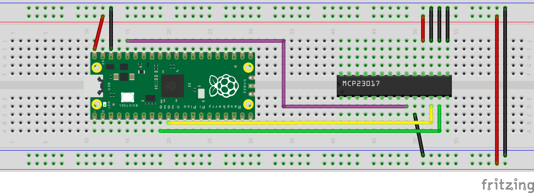
Raspberry Pi PicoとMCP23017にて、下図のような配線をしました。

MCP23017のVss端子に接続している電圧は、Raspberry Pi Picoの出力3.3Vです。
以下、スケッチです。スケッチをたたんでいますので、下の▶をクリックして広げてください。
https://playground.arduino.cc/Main/I2cScanner/ からの引用です。
I2cScanner
// --------------------------------------
// i2c_scanner
//
// Version 1
//    This program (or code that looks like it)
//    can be found in many places.
//    For example on the Arduino.cc forum.
//    The original author is not know.
// Version 2, Juni 2012, Using Arduino 1.0.1
//     Adapted to be as simple as possible by Arduino.cc user Krodal
// Version 3, Feb 26  2013
//    V3 by louarnold
// Version 4, March 3, 2013, Using Arduino 1.0.3
//    by Arduino.cc user Krodal.
//    Changes by louarnold removed.
//    Scanning addresses changed from 0...127 to 1...119,
//    according to the i2c scanner by Nick Gammon
//    https://www.gammon.com.au/forum/?id=10896
// Version 5, March 28, 2013
//    As version 4, but address scans now to 127.
//    A sensor seems to use address 120.
// Version 6, November 27, 2015.
//    Added waiting for the Leonardo serial communication.
//
//
// This sketch tests the standard 7-bit addresses
// Devices with higher bit address might not be seen properly.
//

# include <Wire.h>


void setup()
{
  Wire.begin();

  Serial.begin(9600);
  while (!Serial);             // Leonardo: wait for serial monitor
  Serial.println("\nI2C Scanner");
}


void loop()
{
  byte error, address;
  int nDevices;

  Serial.println("Scanning...");

  nDevices = 0;
  for(address = 1; address < 127; address++ )
  {
    //Serial.print(address);
    // The i2c_scanner uses the return value of
    // the Write.endTransmisstion to see if
    // a device did acknowledge to the address.
    Wire.beginTransmission(address);
    error = Wire.endTransmission();

    if (error == 0)
    {
      Serial.print("I2C device found at address 0x");
      if (address<16)
        Serial.print("0");
      Serial.print(address,HEX);
      Serial.println("  !");

      nDevices++;
    }
    else if (error==4)
    {
      Serial.print("Unknown error at address 0x");
      if (address<16)
        Serial.print("0");
      Serial.println(address,HEX);
    }
  }
  if (nDevices == 0)
    Serial.println("No I2C devices found\n");
  else
    Serial.println("done\n");

  delay(5000);           // wait 5 seconds for next scan
}
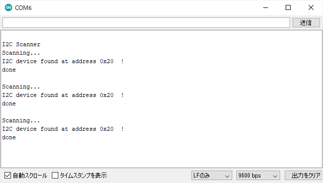
これをコンパイル・書き込みをすると下図のようにシリアル出力されます。
正しく、取得できました!
ちなみにRaspberry Pi Pico側をVBUSに接続しても検知できませんでした。

MCP23017のアドレスは17.18.19をGNDに接続することにより0x20になります。
この3本の組み合わせによりアドレスを0x20~0x27に変えることができます。
すなわち、8個のMC23017を制御することができます。すると128本のI/Oを制御できることになります。いつかLEDキューブを制御してみたいですね。
Raspberry Pi Picoのピン配置には数多くのSDA,SCLがあります。しかし、今回の場合、既定がGP6,GP7(9番ピン,10番ピン)のようです。それ以外ではMCP23017のアドレスを取得できませんでした。
次回は、Arduino Nanoをベースに同じスケッチで試します。