2
1

Delete article

Deleted articles cannot be recovered.

Draft of this article would be also deleted.

Are you sure you want to delete this article?

More than 3 years have passed since last update.

Packet TracerでNetFlowを設定してみる

Posted at

使用環境
Packet Tracer version 8.0.1.0064

既に出来上がっているOSPFネットワークにNetFlowの設定を入れてみたいと思います。
以下の図の構成からスタートします。
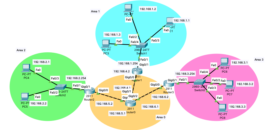
image.png

Area0(オレンジ色)内にあるRouter0にArea2(緑色)からArea3(ピンク色)へ流れるトラフィックをNetflowの対象にしたいと思います。
Netflow出力先はArea2にあるPC4にしたいと思います。

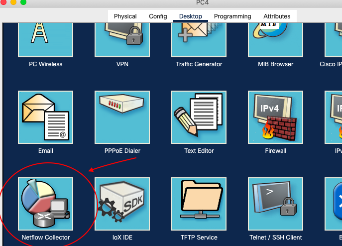
では、まず、PC4にてNetflow Cllectorのサービスをオンにしましょう。

↓デスクトップでNetflow Collectorを選択
Screen Shot 2021-11-16 at 10.21.30 PM.png
↓ServiceがOffになっているので、Onにしましょう。
Screen Shot 2021-11-16 at 10.20.54 PM.png

次にRouter0の設定をします。
インターフェイスは以下のような設定になっています。

Screen Shot 2021-11-16 at 10.27.51 PM.png

ip flow ingressをGigabitEthernet0/0に設定することでそのポートに入ってくるトラフィック、ip flow egressをGigabitEthernet0/2に設定することでそのポートから出ていくトラフィックの情報を監視できるわけです。つまり、Area2からArea3へ流れるトラフィックのことですね。

あと、Netflowの出力先、Flowモニタを設定します。
以下のコマンドを入れればいいです。
Screen Shot 2021-11-16 at 10.28.14 PM.png

設定完了後、PC4からPC6へpingを飛ばします。
ping成功したら、PC4のNetflow Collectorに情報が表示されるはずです。
Screen Shot 2021-11-16 at 10.37.13 PM.png

2
1
0

Register as a new user and use Qiita more conveniently

  1. You get articles that match your needs
  2. You can efficiently read back useful information
  3. You can use dark theme
What you can do with signing up
2
1

Delete article

Deleted articles cannot be recovered.

Draft of this article would be also deleted.

Are you sure you want to delete this article?