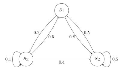
今回目標とする状態遷移図とそのソース
目標の状態遷移図:図
目標の状態遷移図:ソース
node.tex
  \begin{center}
    \begin{tikzpicture}[node/.style={draw, circle, font=\Large, inner sep=6pt}]
      \node[node] (s1) {$s_{1}$};
      \node[node, below right = 3cm and 2cm of s1] (s2) {$s_{2}$};
      \node[node, below left  = 3cm and 2cm of s1] (s3) {$s_{3}$};

      \path[->, >=stealth]
        (s1) edge[left, bend right=10] node{0.8} (s2)
        (s1) edge[left, bend right=10] node{0.2} (s3)
        (s2) edge[right, bend right=10] node{0.5} (s1)
        (s2) edge[loop right, in=315, out=45, looseness=4] node{0.5} (s2)
        (s3) edge[right, bend right=10] node{0.5} (s1)
        (s3) edge[below] node{0.4} (s2)
        (s3) edge[loop left, in=225, out=135, looseness=4] node{0.1} (s3);
    \end{tikzpicture}
  \end{center}
ソースの解説
TikZの導入
TikZの導入
% パッケージのインポート
\usepackage{tikz}

% 使用する関数の宣言
% (最低限これさえ宣言していれば十分だと思われるものを書いています)
\usetikzlibrary{intersections, calc, arrows, positioning, arrows.meta}
図形を描くキャンバスであるtikzpictureについて
\begin{tikzpicture}[node/.style={draw, circle, font=\Large, inner sep=6pt}]
%                  [任意の設定名/.style={設定の羅列}]
今回追加しているオプションは以下の通りです.
-
draw描画する -
circle円を描く -
fontフォント(今回は大きさのみ指定) -
inner sep=6pt円の大きさ
丸を書く\nodeについて
\node[node] (s1) {$s_{1}$};
% \node[設定した任意の設定名] (ラベル) {円の中に書きたい文字列};
- ラベル → 後でそのノードを参照するときに使います
- 文字列 → 数式の環境ではないため
$で囲む必要があります
\node[node, below right = 3cm and 2cm of s1] (s2) {$s_{2}$};
% \node[設定した任意の設定名, ラベルs1に対して下に3cm,右に2cmの位置] (ラベル) {円の中に書きたい文字列};
-
belowとrightの間には,はいりません -
below rightの順番で書いた場合,その順番に対応するように長さをandで区切って書きます
![]() 重要:
重要:tikzpicture内では最後にセミコロン;を付けないとエラーになります!
設定を直接書くこともできます.
% 「node」の設定を「\node」内に直接記述
\node[draw, circle, font=\Large, inner sep=6pt, below right = 3cm and 2cm of s1] (s2) {$s_{2}$};
矢印を引く\pathについて
% ※最初のソースと順番を入れ替えていますが同様の結果が得られます
\path[->, >=stealth]
   (s1) edge[left, bend right=10] node{0.8} (s2)
   (s1) edge[left, bend right=10] node{0.2} (s3)
   (s2) edge[right, bend right=10] node{0.5} (s1)
   (s3) edge[right, bend right=10] node{0.5} (s1)
   % (スタートラベル) edge[数値の場所, 右側に10だけ曲げる] node{書きたい数値} (ゴールラベル)

   (s3) edge[below] node{0.4} (s2)
   % (スタートラベル) edge[数値の場所] node{書きたい数値} (ゴールラベル)

   (s2) edge[loop right, in=315, out=45, looseness=4] node{0.5} (s2)
   (s3) edge[loop left, in=225, out=135, looseness=4] node{0.1} (s3);
   % (スタートラベル) edge[loop 数値の場所, 矢印の開始位置, 矢印の終了位置, たわみ具合] node{書きたい数値} (ゴールラベル)
-
->, >=stealthは「矢印を描く」「その矢印の先端の三角形の種類」を意味しています(ステルス戦闘機のような形だからstealthだそうです) -
bendの曲げたい方向や表示する数値の場所は矢印が進む方向に対する方向(右または左)を指定します -
loopの設定のinやoutは角度を指定しています.角度は通常の180度を開始位置として時計回りに考えてください -
loopの設定のloosenessはループのたわみ具合を表しています.好きなたわみ具合を探してみてください
![]() 改行していますが命令としては1行です.したがってセミコロン
改行していますが命令としては1行です.したがってセミコロン;は最後の行のみに付けてください!
一括で書かずに1行ずつ書くこともできます.
\path[->, >=stealth] (s1) edge[left, bend right=10] node{0.8} (s2);
\path[->, >=stealth] (s1) edge[left, bend right=10] node{0.2} (s3);
まとめ
今回は私が初めて$\LaTeX$で直接図形を描くやり方を学んだので備忘録としてまとめました.
オプション一つひとつがどのような意味であるか明確に書いたつもりです.
