はじめに
今回は、こちらの記事で導出した「台車型倒立振子(CartPole)」の運動モデルを使用して、倒立状態をキープするための「最適レギュレータ」の設計と、それを組み込んだ閉ループ系のシミュレーション方法について説明したいと思います。
最適レギュレータとは
最適レギュレータとは、線形時不変なシステムに対して「状態フィードバック」を行うことを考えた際に、システムの応答が「最適(いいかんじ)」になるようにフィードバックゲインを決める設計手法、またはその制御器のことを指します。
もう少し具体的に説明してみましょう。
状態フィードバック
以下の状態方程式で表される線形時不変なシステムを考えます。ここで、$\boldsymbol{x}$は状態ベクトル、$\boldsymbol{u}$は入力ベクトルです。また、システムは可制御、状態はすべて直接観測できる(出力=状態)ものとします。
\dot{\boldsymbol{x}} = A\boldsymbol{x} + B\boldsymbol{u} \\
\boldsymbol{x} \in \mathcal{R}^n, \boldsymbol{u} \in \mathcal{R}^r, A \in \mathcal{R}^{n \times n}, B \in \mathcal{R}^{n \times r}
次に、フィードバック制御により状態$\boldsymbol{x}$を安定化、つまり何らかの要因で$\boldsymbol{x}$の値が乱されたとき、速やかに$0$に戻すように制御すること(今回の問題で言えば、振り子が倒立状態をキープするように台車を動かすこと)を考えます。
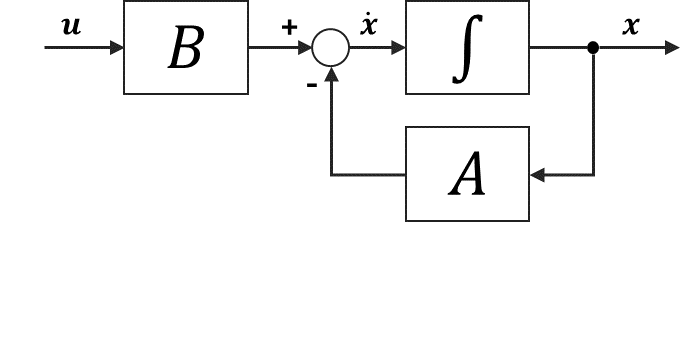
このとき、フィードバックゲインを$K \in \mathcal{R}^{r \times n}$として、入力を$\boldsymbol{u}=-K\boldsymbol{x}$と定義します。すると、閉ループ系の状態方程式は
\dot{\boldsymbol{x}} = A\boldsymbol{x} + B(-K\boldsymbol{x})=(A-BK)\boldsymbol{x}
となります。これを「状態フィードバック」といい、同様に図で表すと以下のようになります。

最適レギュレータによるゲイン計算
さて、ここで問題となるのは$K$の決め方です。上の閉ループ系($\dot{\boldsymbol{x}}=(A-BK)\boldsymbol{x}$)を新たなシステムと考えれば、$A-BK$が安定となるように($A-BK$の固有値の実部が負になるように)決めればいいわけですが、そのような$K$は一意ではありません。
試行錯誤で決めてもよいのですが、ここでは比較的簡単に設計でき、かつ高い性能を得られる方法である「最適レギュレータ(LQR:Linear Quadratic Regulator)」を紹介します。
最適レギュレータは、以下の二次形式の評価関数
J = \int _0^\infty \left(\boldsymbol{x}^T Q \boldsymbol{x} + \boldsymbol{u}^T R \boldsymbol{x} \right) \mathrm{d}t \\
Q \in \mathcal{R}^{n \times n}, R \in \mathcal{R}^{r \times r}
に対して、これを最小化するためのゲイン$K$を計算します。ここで、$Q,R$は「重み行列」と呼ばれる設計パラメータで、$Q$は半正定対称行列1、$R$は正定対称行列2です。評価関数の各項はそれぞれ以下の意味を持ちます。
- $\boldsymbol{x}^T Q \boldsymbol{x}$:状態の大きさ($Q$を大きくする ⇒ 0への収束が速くなる)
- $\boldsymbol{u}^T R \boldsymbol{x}$:入力の大きさ($R$を大きくする ⇒ 入力=エネルギー消費が小さくなる)
さて、$J$を最小化する$K$を計算するには、以下の「Riccati方程式3」を$P$について解く必要があります。Pythonでは、Scipyのsolve_continuous_are()関数で計算できます4。
PA+A^TP-PBR^{-1}B^TP+Q=0
ゲイン$K$は、Riccati方程式の解$P$を用いて次式で求められます。
K=R^{-1}B^TP
求めた$K$を使って、実際に$A-BK$の固有値を確認するのもいいでしょう。
一度計算してしまえば、$A,B,Q,R$が変化しない限りフィードバックゲインを計算しなおす必要はありません。したがって、制御器の実装そのものは通常の状態フィードバックと同一です。
重み行列の決め方
重み行列$Q,R$は、通常は各成分が正の対角行列とします。
Q = \left[ \begin{matrix} q_1^2 & 0 & \cdots & 0 \\ 0 & q_2^2 & 0 & 0 \\ \vdots & \vdots & \ddots & \vdots \\ 0 & 0 & 0 & q_n^2 \end{matrix} \right],
R = \left[ \begin{matrix} r_1^2 & 0 & \cdots & 0 \\ 0 & r_2^2 & 0 & 0 \\ \vdots & \vdots & \ddots & \vdots \\ 0 & 0 & 0 & r_n^2 \end{matrix} \right]
添え字は状態ベクトル・入力ベクトルの要素に対応しており、例えば$q_2^2$であれば$x_2$の重みを表すことになります。
ただし、重みの決め方には明確な指針がないため、基本的には動作を見ながら試行錯誤でチューニングしていくことになります。まずは単位行列からスタートするのがいいでしょう(私の場合は$R$を単位行列固定にしてしまうことが多いです)。
今回の場合であれば、$\theta,\dot{\theta}$の重みを大きくしてあげると望ましい結果が得られやすいかと思います。ただし、重みをあまり大きくするとゲインが高くなり、ノイズの影響を受けやすくなるので注意。
倒立振子の運動モデル
本項は前回の記事のおさらいです。

上の図に示す台車型倒立振子を考え、状態ベクトルと入力ベクトルを以下のとおり定義します。
\boldsymbol{x}=[ p, \theta, \dot{p}, \dot{\theta} ]^T, \boldsymbol{u}=[ F ] \\
このとき、非線形状態方程式は以下のように表されます。
\dot{\boldsymbol{x}} = f(\boldsymbol{x},\boldsymbol{u}) =
\left[\begin{matrix}\dot{p}\\
\dot{\theta}\\
\frac{- l m_{2} \operatorname{sin}\left(\theta\right) \dot{\theta}^{2} + g m_{2} \operatorname{sin}\left(\theta\right)\operatorname{cos}\left(\theta\right) + F}{m_{1} + m_{2} \operatorname{sin}^{2}\left(\theta\right)}\\\frac{g \left(m_{1} + m_{2}\right) \operatorname{sin}\left(\theta\right) - \left(l m_{2} \operatorname{sin}\left(\theta\right) \dot{\theta}^{2} - F\right) \operatorname{cos}\left(\theta\right)}{l \left(m_{1} + m_{2} \operatorname{sin}^{2}\left(\theta\right)\right)}\end{matrix}\right]
これを線形化すると
\dot{\boldsymbol{x}} = A\boldsymbol{x} + B\boldsymbol{u} =
\left[\begin{matrix}0 & 0 & 1 & 0\\0 & 0 & 0 & 1\\0 & \frac{g m_{2}}{m_{1}} & 0 & 0\\0 & \frac{g \left(m_{1} + m_{2}\right)}{l m_{1}} & 0 & 0\end{matrix}\right] \boldsymbol{x} +
\left[\begin{matrix}0\\0\\\frac{1}{m_{1}}\\\frac{1}{l m_{1}}\end{matrix}\right] \boldsymbol{u}
となります。
実装
最適レギュレータを計算してシミュレーションを行うコードは以下のようになります(大部分はプロット用です)。
演算周期は50[ms]とし、重み行列は以下のように設定してみました。
Q = \left[ \begin{matrix} 1 & 0 & 0 & 0 \\ 0 & 100 & 0 & 0 \\ 0 & 0 & 1 & 0 \\ 0 & 0 & 0 & 10 \end{matrix} \right],
R = \left[ 1 \right]
# -*- coding: utf-8 -*-

import matplotlib.pyplot as plt
import numpy as np
from scipy import linalg

class InvertedPendulum:
    """
    倒立振子モデル
    """
    g = 9.80665

    def __init__(self, m1, m2, l):
        self.m1 = m1
        self.m2 = m2
        self.l = l

    def state_equation(self, x, F):
        '''
        非線形モデル
        '''
        p = x[0]
        theta = x[1]
        dp = x[2]
        dtheta = x[3]

        dx = np.zeros(4)

        dx[0] = dp
        dx[1] = dtheta
        dx[2] = (-self.l*self.m2*np.sin(theta)*dtheta**2 + InvertedPendulum.g*self.m2*np.sin(2*theta)/2 + F)/(self.m1 + self.m2*np.sin(theta)**2)
        dx[3] = (InvertedPendulum.g*(self.m1 + self.m2)*np.sin(theta) - (self.l*self.m2*np.sin(theta)*dtheta**2 - F)*np.cos(theta))/(self.l*(self.m1 + self.m2*np.sin(theta)**2))

        return dx

    def model_matrix(self):
        '''
        線形モデル
        '''
        A = np.array([
                [0, 0, 1, 0],
                [0, 0, 0, 1],
                [0, InvertedPendulum.g*self.m2/self.m1, 0, 0],
                [0, InvertedPendulum.g*(self.m1 + self.m2)/(self.l*self.m1), 0, 0]
            ])

        B = np.array([
                [0],
                [0],
                [1/self.m1],
                [1/(self.l*self.m1)]
            ])

        return A, B

def lqr(A, B, Q, R):
    '''
    最適レギュレータ計算
    '''
    P = linalg.solve_continuous_are(A, B, Q, R)
    K = linalg.inv(R).dot(B.T).dot(P)
    E = linalg.eigvals(A - B.dot(K))

    return P, K, E

def plot_graph(t, data, lbls, scls):
    '''
    時系列プロット
    '''

    fig = plt.figure()

    nrow = int(np.ceil(data.shape[1] / 2))
    ncol = min(data.shape[1], 2)

    for i in range(data.shape[1]):
        ax = fig.add_subplot(nrow, ncol, i + 1)
        ax.plot(t, data[:,i] * scls[i])

        ax.set_xlabel('Time [s]')
        ax.set_ylabel(lbls[i])
        ax.grid()
        ax.set_xlim(t[0], t[-1])

    fig.tight_layout()

def draw_pendulum(ax, t, xt, theta, l):
    '''
    倒立振子プロット
    '''

    cart_w = 1.0
    cart_h = 0.4
    radius = 0.1

    cx = np.array([-0.5, 0.5, 0.5, -0.5, -0.5]) * cart_w + xt
    cy = np.array([0.0, 0.0, 1.0, 1.0, 0.0]) * cart_h + radius * 2.0

    bx = np.array([0.0, l * np.sin(-theta)]) + xt
    by = np.array([cart_h, l * np.cos(-theta) + cart_h]) + radius * 2.0

    angles = np.arange(0.0, np.pi * 2.0, np.radians(3.0))
    ox = radius * np.cos(angles)
    oy = radius * np.sin(angles)

    rwx = ox + cart_w / 4.0 + xt
    rwy = oy + radius
    lwx = ox - cart_w / 4.0 + xt
    lwy = oy + radius

    wx = ox + float(bx[1])
    wy = oy + float(by[1])

    ax.cla()
    ax.plot(cx, cy, "-b")
    ax.plot(bx, by, "-k")
    ax.plot(rwx, rwy, "-k")
    ax.plot(lwx, lwy, "-k")
    ax.plot(wx, wy, "-k")
    ax.axis("equal")
    ax.set_xlim([-cart_w, cart_w])
    ax.set_title("t:%5.2f x:%5.2f theta:%5.2f" % (t, xt, theta))

def main():
    # モデル初期化
    ip = InvertedPendulum(m1 = 1.0, m2 = 0.1, l = 0.8)

    # 最適レギュレータ計算
    A, B = ip.model_matrix()
    Q = np.diag([1, 100, 1, 10])
    R = np.eye(1)

    P, K, E = lqr(A, B, Q, R)

    # シミュレーション用変数初期化
    T = 10
    dt = 0.05
    x0 = np.array([0, 0.1, 0, 0]) * np.random.randn(1)

    t = np.arange(0, T, dt)
    x = np.zeros([len(t), 4])
    u = np.zeros([len(t), 1])

    x[0,:] = x0
    u[0] = 0

    # シミュレーションループ
    for i in range(1, len(t)):
        u[i] = -np.dot(K, x[i-1,:]) + np.random.randn(1)
        dx = ip.state_equation(x[i-1,:], u[i])
        x[i,:] = x[i-1,:] + dx * dt


    # 時系列データプロット(x,u)
    plt.close('all')

    lbls = (r'$p$ [m]', r'$\theta$ [deg]', r'$\dot{p}$ [m/s]', r'$\dot{\theta}$ [deg/s]')
    scls = (1, 180/np.pi, 1, 180/np.pi)
    plot_graph(t, x, lbls, scls)

    lbls = (r'$F$ [N]',)
    scls = (1,)
    plot_graph(t, u, lbls, scls)

    # アニメーション表示
    fig, ax = plt.subplots()
    for i in range(len(t)):
        draw_pendulum(ax, t[i], x[i,0], x[i,1], ip.l)
        plt.pause(0.01)

if __name__ == '__main__':
    main()
実行結果
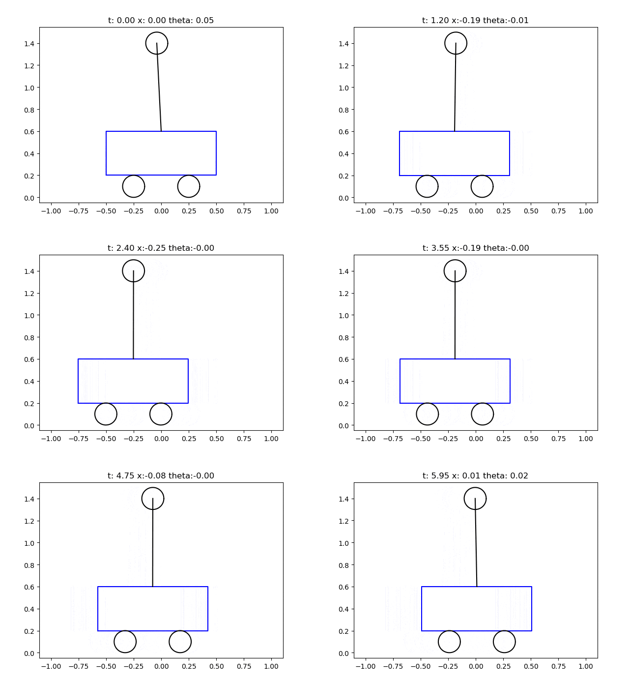
シミュレーション結果をアニメーションで確認できます。多少ふらついても振子が倒立状態をキープしていますね(少し動きに乏しいかな…)。
おわりに
いかがでしょうか。後半はやや駆け足だったかもしれません(シミュレーションの部分はほとんど説明できていない)。最適レギュレータが登場したのは1960年代ですが、多入力多出力系の制御手法としては現在でも十分通用するかと思います。
次はモデル予測制御あたりを紹介できたらいいですね。

