three.jsではTHREE.Lineで線を書くことができます。この線の太さはLineBasicMaterial#linewidthで設定できます。しかし、リンク先に書いてあるようにほとんどのプラットフォームでは設定によらず太さが1になってしまいます(具体的にどのプラットフォームだと駄目なのかは検証していないのでよくわかってないです...)。
太さのある線を描画するためには線に沿ってメッシュを生成して描画する必要があります。この記事では、その方法について解説します。
なお、すでにTHREE.MeshLineという同様の操作により太さのある線を簡単に描画できるライブラリが存在しているので、要件を満たせるのであればそちらを使用したほうがいいと思います。
今回作成したソースコードはGitHubに置いてあります。
aadebdeb/three-mesh-line-sample: Three.js Mesh Line Sample
使用したthree.jsのバージョンはr124です。
太さのある線を描画するための手順としては、以下のようになります。
- ベースとなる線を作成する
- 線に沿ってGeometryを作成する
- 線を描画するためのMaterialを作成する
- 作成したGeometryとMaterialからMeshを作成してSceneに追加する
- (レンダリングループ内で必要があれば)、Geometryを更新して線を動かす
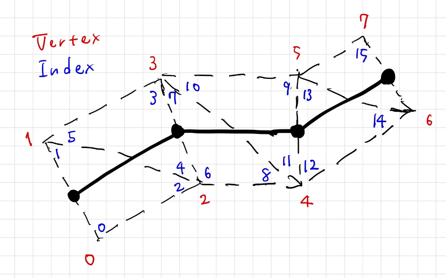
作成するメッシュのイメージとしては以下のようになります。真ん中の実線がベースとなる線で、その周りの破線がメッシュを表しています。図のように線に沿って四角形のメッシュを連続して並べることで太さのある線を表現します。
まずはベースとなる線を作成します。createLineSegmentsメソッドでsegmentNum個の点を繋いだ適当な線を配列として生成しています。
const createLineSegments = (segmentNum) => {
  const segments = new Float32Array(segmentNum * 3);
  for (let i = 0; i < segmentNum; ++i) {
    segments[3 * i] = 50.0 * Math.sin(0.032 * i + 0.35) * Math.sin(-0.029 * i + 4.86); // x
    segments[3 * i + 1] = 50.0 * Math.sin(i * 0.041 - 1.96) * Math.sin(0.015 * i + 3.23); // y
    segments[3 * i + 2] = 50.0 * Math.sin(i * 0.078 - 5.21) * Math.sin(-0.122 * i + 1.51); // z
  }
  return segments;
}

const segmentNum = 1000;
const segments = createLineSegments(segmentNum);
作成した線に沿ってメッシュを張るように、Geometryを作成します。まずはGeomertyを構成する頂点の情報を格納する配列を生成します。positionsに対応したベースとなる線の頂点の位置、prevPositionsに一つ前のベースとなる線の頂点の位置、nextPositionsに一つ先のベースとなる線の頂点の位置を格納しています。また、signsにベースとなる線の頂点に対して上にあるか下にあるかを格納しています。この段階では、ベースとなる線の情報だけを入れておき、正しい位置への配置はこれらの情報をもとに頂点シェーダーで行います。
const createLineGeometryAttributes = (segments) => {
  const segmentNum = segments.length / 3;
  const vertexNum = 2 * segmentNum;
  const indexNum = 6 * (segmentNum - 1);
  const positions = new Float32Array(vertexNum * 3);
  const prevPositions = new Float32Array(vertexNum * 3);
  const nextPositions = new Float32Array(vertexNum * 3);
  const signs = new Float32Array(vertexNum);
  const indices = new Uint16Array(indexNum);

  const setPosAt = (pos, i, j) => {
    pos[6 * i] = pos[6 * i + 3] = segments[3 * j];
    pos[6 * i + 1] = pos[6 * i + 4] = segments[3 * j + 1];
    pos[6 * i + 2] = pos[6 * i + 5] = segments[3 * j + 2];
  };

  for (let i = 0; i < segmentNum; ++i) {
    setPosAt(positions, i, i);
    setPosAt(prevPositions, i, i !== 0 ? i - 1 : 0);
    setPosAt(nextPositions, i, i !== segmentNum - 1 ? i + 1 : segmentNum - 1);
    signs[2 * i] = 1.0;
    signs[2 * i + 1] = -1.0;
  }

  for (let i = 0; i < segmentNum - 1; ++i) {
    indices[6 * i] = 2 * i;
    indices[6 * i + 1] = indices[6 * i + 5] = 2 * i + 1;
    indices[6 * i + 2] = indices[6 * i + 4] = 2 * i + 2;
    indices[6 * i + 3] = 2 * i + 3;
  }

  return {
    positions,
    prevPositions,
    nextPositions,
    signs,
    indices,
  }
};

const attributes = createLineGeometryAttributes(segments);
作成した配列はAttributeとしてGeometryに紐づけおきます。
const geometry = new THREE.BufferGeometry();
const positionAttribute = new THREE.BufferAttribute(attributes.positions, 3);
geometry.setAttribute('position', positionAttribute);
const prevPositionAttribute = new THREE.BufferAttribute(attributes.prevPositions, 3);
geometry.setAttribute('prevPosition', prevPositionAttribute);
const nextPositionAttribute =  new THREE.BufferAttribute(attributes.nextPositions, 3);
geometry.setAttribute('nextPosition', nextPositionAttribute);
geometry.setAttribute('sign', new THREE.BufferAttribute(attributes.signs, 1));
geometry.setIndex(new THREE.BufferAttribute(attributes.indices, 1));
Geometryが準備できたので、次にMaterialを作成します。頂点シェーダーでは、まずposition・prevPosition・nextPositionから線がどの方向に進んでいるか(posDir)を求めています。この値とカメラの方向(viewDir)でクロス積をとることにより、線の上方向(linePlaneDir)が求まります。これにsignを掛けてベースとなる線の頂点位置に足すことで正しい位置に頂点が置かれて、面でできた線が常にカメラを向くようになります。
const vertexShader =
`attribute vec3 position;
attribute vec3 prevPosition;
attribute vec3 nextPosition;
attribute float sign;

uniform mat4 modelMatrix;
uniform mat4 viewMatrix;
uniform mat4 projectionMatrix;
uniform vec3 cameraPosition;

uniform float lineWidth;

void main() {
  vec4 worldPos = modelMatrix * vec4(position, 1.0);
  vec4 worldPrevPos = modelMatrix * vec4(prevPosition, 1.0);
  vec4 worldNextPos = modelMatrix * vec4(nextPosition, 1.0);
  vec3 prevPosDir = worldPos.xyz - worldPrevPos.xyz;
  prevPosDir = length(prevPosDir) > 1e-8 ? normalize(prevPosDir) : vec3(0.0); // to avoid division by zero
  vec3 nextPosDir = worldNextPos.xyz - worldPos.xyz;
  nextPosDir = length(nextPosDir) > 1e-8 ? normalize(nextPosDir) : vec3(0.0); // to avoid division by zero
  vec3 posDir = prevPosDir + nextPosDir;
  vec3 viewDir = cameraPosition - worldPos.xyz;
  vec3 linePlaneDir = cross(viewDir, posDir);
  linePlaneDir = length(linePlaneDir) > 1e-8 ? normalize(linePlaneDir) : vec3(0.0); // to avoid division by zero
  worldPos.xyz += lineWidth * 0.5 * sign * linePlaneDir;
  gl_Position = projectionMatrix * viewMatrix * worldPos;
}
`;

const fragmentShader =
`precision highp float;

uniform vec3 color;

void main() {
  gl_FragColor = vec4(color, 1.0);
}
`

const material = new THREE.RawShaderMaterial({
  vertexShader: vertexShader,
  fragmentShader: fragmentShader,
  uniforms: {
    color: { value: new THREE.Color(0xffffff) },
    lineWidth: { value: 1.0 }
  },
});
あとは、作成したGeometryとMaterialをもとにMeshを作成してシーンに追加するだけです。
const mesh = new THREE.Mesh(geometry, material);
scene.add(mesh);
結果として、以下のように描画されます。
サンプルはこちらです。
https://aadebdeb.github.io/three-mesh-line-sample/index.html
次のように頂点配列を更新してBufferAttribute#needsUpdateをtrueにすること変更を反映できるので、線をアニメーションさせることも可能です。
const createLineSegments = (segmentNum) => {
  const segments = new Float32Array(segmentNum * 3);
  for (let i = 0; i < segmentNum; ++i) {
    segments[3 * i] = (i / segmentNum - 0.5) * 100.0;
    segments[3 * i + 1] = 30.0 * Math.cos(0.3 * segments[3 * i]);
    segments[3 * i + 2] = 0;
  }
  return segments;
}

const updateLineSegments = (segments, offset) => {
  const segmentNum = segments.length / 3;
  for (let i = 0; i < segmentNum; ++i) {
    segments[3 * i] = (i / segmentNum - 0.5) * 100.0;
    segments[3 * i + 1] = 30.0 * Math.cos(0.3 * segments[3 * i] + 10.0 * offset);
    segments[3 * i + 2] = 0;
  }
};

...

const updateLineGeometryAttributes = (segments, attributes) => {
  const segmentNum = segments.length / 3;
  const vertexNum = 2 * segmentNum;

  const setPosAt = (pos, i, j) => {
    pos[6 * i] = pos[6 * i + 3] = segments[3 * j];
    pos[6 * i + 1] = pos[6 * i + 4] = segments[3 * j + 1];
    pos[6 * i + 2] = pos[6 * i + 5] = segments[3 * j + 2];
  };

  for (let i = 0; i < segmentNum; ++i) {
    setPosAt(attributes.positions, i, i);
    setPosAt(attributes.prevPositions, i, i !== 0 ? i - 1 : 0);
    setPosAt(attributes.nextPositions, i, i !== segmentNum - 1 ? i + 1 : segmentNum - 1);
  }
}

...

const updateGeometry = (time) => {
  updateLineSegments(segments, time);
  updateLineGeometryAttributes(segments, {
    positions: positionAttribute.array,
    prevPositions: prevPositionAttribute.array,
    nextPositions: nextPositionAttribute.array,
  });
  positionAttribute.needsUpdate = true;
  nextPositionAttribute.needsUpdate = true;
  prevPositionAttribute.needsUpdate = true;
};

...

const clock = new THREE.Clock();
const animate = () => {
  requestAnimationFrame(animate);
  const time = clock.getElapsedTime();
  updateGeometry(time);
  renderer.render(scene, camera);
}
animate();
頂点を更新する場合のサンプルはこちらです。
https://aadebdeb.github.io/three-mesh-line-sample/update.html