はじめに
こんにちは、水谷です。今回はNotch上で様々なノードカテゴリを
横断する方法について書いてみたいと思います。初級者から中級者向けの内容です。
ここにシーンファイルをアップロードしてあるので、実際にシーンを触りながら読んで頂くと
理解が深まるかもしれません。
DFX DOWNLOAD 
I'm going to try to explain the inter-connectivity of different node types.
I uploaded the dfx here. So please feel free to play with it(CC0).
それぞれ単独でも十分に強力なノード群からなるnotch、
リッチなインタラクティブかつリアルタイムなビジュアルは一つの
ノードグループでも完結して制作することができます。
Notch nodes are generally pretty powerful, in general.
You can build stunning interactive, real time visuals within the given node category.
You can finish your work only with the particle nodes and it's awesome.
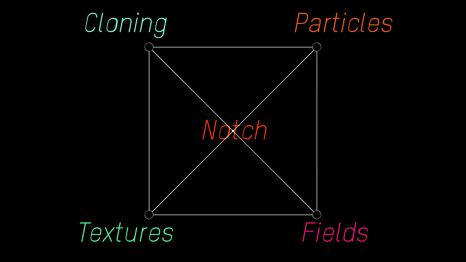
Notch = Versatility

これらのノードの中にはノードカテゴリの垣根を超えてお互いに接続できるものがあります。
思いつく一番シンプルな組み合わせを挙げるとすれば、
particle nodeとCloner(Clone To Particle Node)の組み合わせだと思います。
なので、実際に見てみましょう。
At the same time many notch nodes are built inter connectivity of different node-types in mind.
The simplest example might be the combination of particle nodes and Cloner(clone to particle node).
This relatively new node(as replacement of mesh renderer particle node) enables to create instances of
3d geometry(3D object/Shape 3D etc) for assigned particles.
Clone to Particles
 Particleと Clonerは色が違うからといってお互いに干渉することは不可能かと言えば
そうではなく、例えばこのClone To Particle Nodeを使えば、
パーティクルのそれぞれのポイントを3Dジオメトリに置き換えて表示することができます。
上記は実際にグリッド状に配置されたパーティクルをスフィアのインスタンスに置き換えてみたところです。
But there's much more of this kind in notch.
You can combine so many node-types and go back and forth within the different node-types, like jugglers do.
## Clone to Particle 詳細
 Clone To Particles Nodeのinputを見てみると、 Particle Nodeとオーバーレイが表示されます。
これにより、Clone To Particles NodeはParticleをインプットとして
扱うことができるのだな、と知ることができます(この場合は Particle Rootをフィードしていますね)。
If you hover the mouse cursor on the input of Clone To Particles, it'll indicate it accepts Particle Node as input. In this manner you may know which node type could be fed as input.
## 小まとめ
まずは基本のClone To Particles。
Particle Rootからアウトする、という手法がちょっとトリッキーですね。
Ok, this is pretty basic, but wiring from the Root node might be tricky.
## Advection I
 こちらはFieldとParticleをかけ合わせた例です。
パーティクルが外側に押し出される様子が見て取れるかと思います。
煙のような流体のモーションに注目してください。
こういった有機的・流体的な動きはParticleノード内で完結した場合、なかなか難しい表現だと思います。
Here's fairly simple example of combining field node and particle node.
You can see particles within the sphere get pushed outwards.
Please notice the fluid or smoke-alike motion here.
You can never achieve this only in particle node group.
In this example, particle motion is driven by velocity field and this is called advection.
## Advection II

実際にネットワークグラフがどうなっているのかを見てみましょう。
まず、下部の紫のField Rootから見てみると、Velocity Affector, Turbulence Affectorの2つがメインのモーションを
作っています。最後にFluid Affectorがあり、これが流体らしさを追加するキーとなる重要なノードになります。
こちらはFieldとParticleをかけ合わせた例です。
パーティクルが外側に押し出される様子が見て取れるかと思います。
煙のような流体のモーションに注目してください。
こういった有機的・流体的な動きはParticleノード内で完結した場合、なかなか難しい表現だと思います。
Here's fairly simple example of combining field node and particle node.
You can see particles within the sphere get pushed outwards.
Please notice the fluid or smoke-alike motion here.
You can never achieve this only in particle node group.
In this example, particle motion is driven by velocity field and this is called advection.
## Advection II

実際にネットワークグラフがどうなっているのかを見てみましょう。
まず、下部の紫のField Rootから見てみると、Velocity Affector, Turbulence Affectorの2つがメインのモーションを
作っています。最後にFluid Affectorがあり、これが流体らしさを追加するキーとなる重要なノードになります。
次に上部のParticle Rootを見てみると、パーティクルの動きに影響を及ぼすAffectorはField Affectorの1つしかありません。
Field Affectorのinputを見てみると、Field Rootからのアウトプットが繋がっているのが見て取れると思います。
(先程のClone To ParticlesがParticle Rootをinputとして取っていたのに似ていますね。)
こうしてParticlesがFieldにより動いているわけですね。
Let's take a closer look and check how the network view looks like:
Actually the particle root contains only one affector(Field Affector) which drives motion of particles.
And you see the input source of Field Affector is coming from Field root.
And again, Field Root has three Affectors which are:
The Velocity Affector, Turbulence Affector and last but not least, the Fluid Affector.
These three Affectors are responsible for particle motion in this example.
Advection 小まとめ(verdict)
多くのDCCアプリケーションではFluid Dynamicsの挙動を詰めてからParticlesを添わせる、という
2ステップのワークフローになる事がままありますが、notchではこれがリアルタイムに同時にできます。
これは非常にパワフルなフィーチャーなので、パーティクルに有機的な挙動を与えたいときには
非常に有効な手法と言えるでしょう。
In most of DCC application these kind of simulation is so expensive that you need to cache the
fluid simulation first then you can see advected movement of particles.
Notch does this in real time. At the first time I saw this, I was literally blown away.
Render to Texture I
 次にRender To Textureについてカバーしたいと思います。
このノードはRender To Texture以下に接続されているchildren nodesをレンダリングし、それを
Textureのストリームとして保存し、MaterialのTextureや、様々なノードカテゴリ内で他の用途に使用できると言うものです。
これにより、テクスチャをプロシージャルかつリアルタイムに生成することができます。
Okay let's move on.
The next topic I'd like to cover, in terms of inter connectivity, is the render to texture node.
This node enables you to render current scene as continuous bitmap stream and use them as texture.
So you can create textures in procedural way and it's real time, isn't this sweet?
Render to Texture II
Render Texture Root以下に通常の要領でシーンを作っていきます。
Cameraは1つ必ず必要で、このViewからの絵が実際にテクスチャとして保存されます。
Render To Texture Rootから、このテクスチャがMaterialのDiffuse Textureに送られ、
それによりPlane上に「カメラから見た絵(つまりノイズのテクスチャのついた球体)」がマッピングされているわけです。
Node-Manner is relatively simple.
Just connect Render Texture node with at least one camera.
This camera will the render cam.
The other scene objects, which should be rendered, should be also connected into Render To Texture Node.
Render To Texture: Verdict
考え方としてやや馴染みが無いので慣れるまで使いにくいですが、強力なワークフローです。
最近実業務でとても有意義に使えたシナリオとして、球体プロジェクションのモック制作で
VRcamから見たシーン全体を360度レンダリングし、そのテクスチャを球体にマッピングすることで、
球体マッピングのコンテンツなどをリアルタイムに制作したりしました。
Scene Reading: Inhale/Exhale(by me)
最後にこのページのタイトル絵になっている習作(Inhale/Exhale)を読み解いてみましょう。
このページで紹介したテクニックを元に作られていて、シーンビルディングの順序としては以下の通り:
1)Field RootからVelocity Fieldの作成
2)Particle Root以下にField Affectorを置き、そのinputとField Rootを繋ぐ。
3)これによりParticleの動きはFieldのVelocity Fieldにより制御されます。
4)Clone To Particleを作成、Cloner To ParticlesのinputとParticle Rootを繋ぐ。
5)これにより、Clonerに接続された3DジオメトリがParticleのインスタンスとして表示されます。
基本的な流れとしてはこんな感じでしょうか。
さらに追加の要素として
6)Particle Root以下にPoint Rendererを置き、Attribute Shading(Magnitude Velocity)により
移動量の大きいパーティクルは白く、小さいパーティクルは黒く描いています。
7)これをRender To Textureにより、テスクチャとして保存
8)このTextureにImage Effects(IMAG)をかけ、スムーズにします。
9)プロセス後の白黒イメージを Cloner以下のImage Affectorのinputに繋ぎ
10)移動量の速いパーティクルにはZ軸にスケールがかかるようになっています。
全体としてみると Field/Particle/Cloner/Render To Texture/IMAGの5要素が連携している
事になります。
Network graph

ネットワークにカテゴリをまたいで繋がっている関係をマーキングするとこのような感じになるかと思います。
横断するワイヤが多くなるとノードグラフの可読性が悪くなるので、できるだけそれぞれのグループを
コンパクトに配置したり、ラインの重なりができる限り起きないように工夫しています。
Verdict
さて、この記事では「いろいろなノードをつないでみよう」
というテーマで書いてみました。
これはnotchを使う際には必須の考え方なのですが、慣れないうちは
それぞれの要素を同時に管理するのが大変ですね。
一方、慣れてくるに従ってこのチェーンを複雑化したり再帰的に使ったりすることが
できるようになります。これらは勿論元々notch内で想定されているワークフローなので
全く新しい物でもなんでもないのですが、様々なノードの組み合わせ方がわかると
Trail Rendererや、Geometey Connection Rendererの合せ技など、
「あぁ、notchでサクっと作ったっぽいね」という印象からはもう少し違った
複雑な挙動のビジュアルを作れるようになります。
思いもよらない発想やビジュアルが生まれてくるので、
この記事がみなさんのワークフローを一段推し進める一助になればと思います。
かしこ。


