#Pythonで学ぶ制御工学< P・PD・PID制御(閉ループ系) >
はじめに
基本的な制御工学をPythonで実装し,復習も兼ねて制御工学への理解をより深めることが目的である.
その第15弾として「P・PD・PID制御(閉ループ系)」を扱う.
PID制御の概要
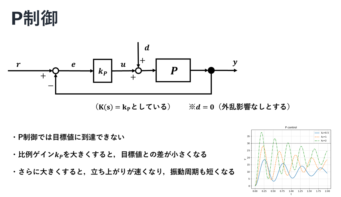
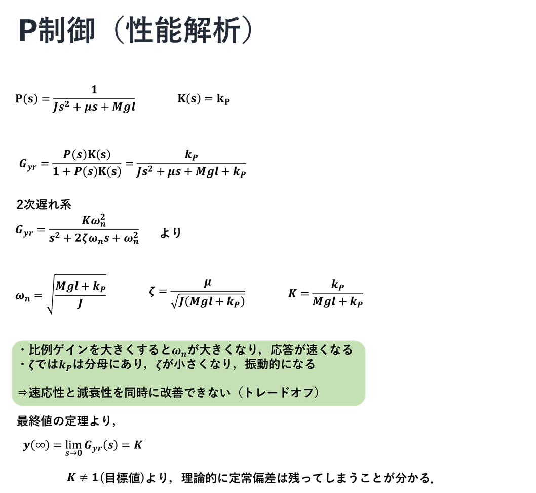
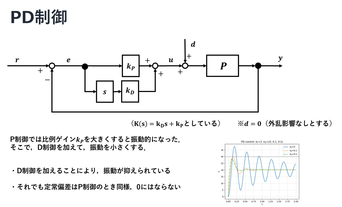
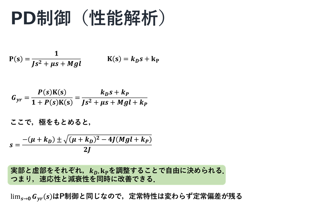
まずはじめに,ここで扱う例題と閉ループ系PID制御の概要について以下に示す.
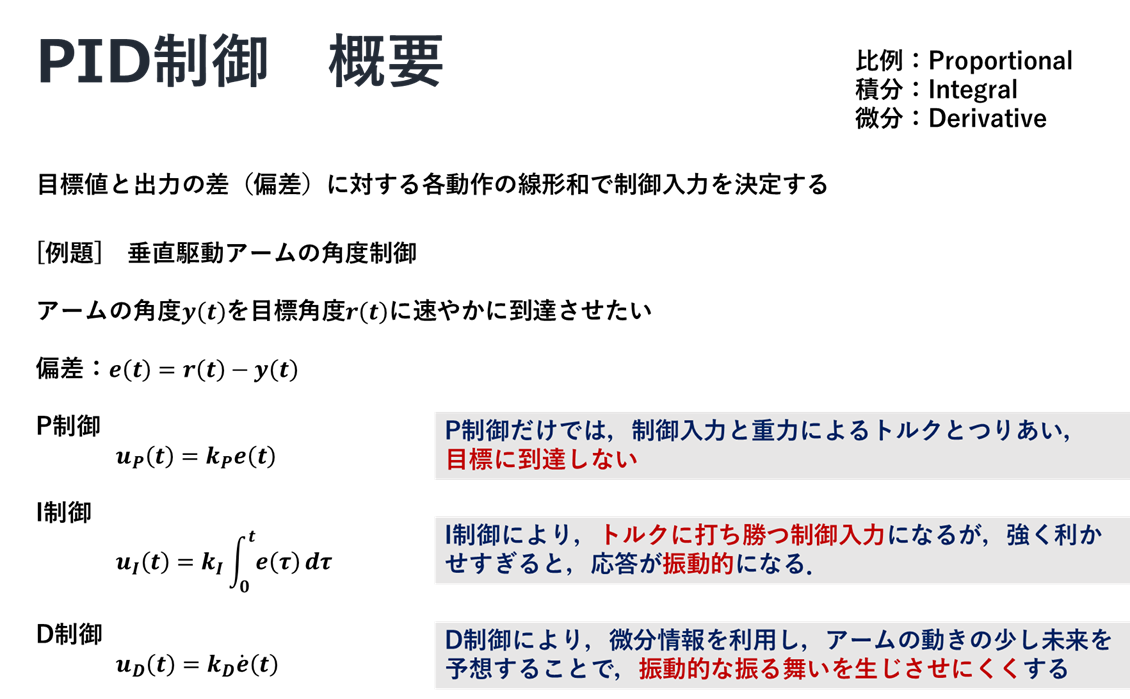
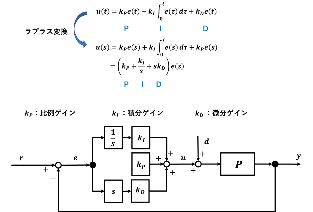
以下では,P制御 → PD制御 → PID制御という順でさらに細かく理解していくことで,それぞれの特徴をつかんでいく.
P制御
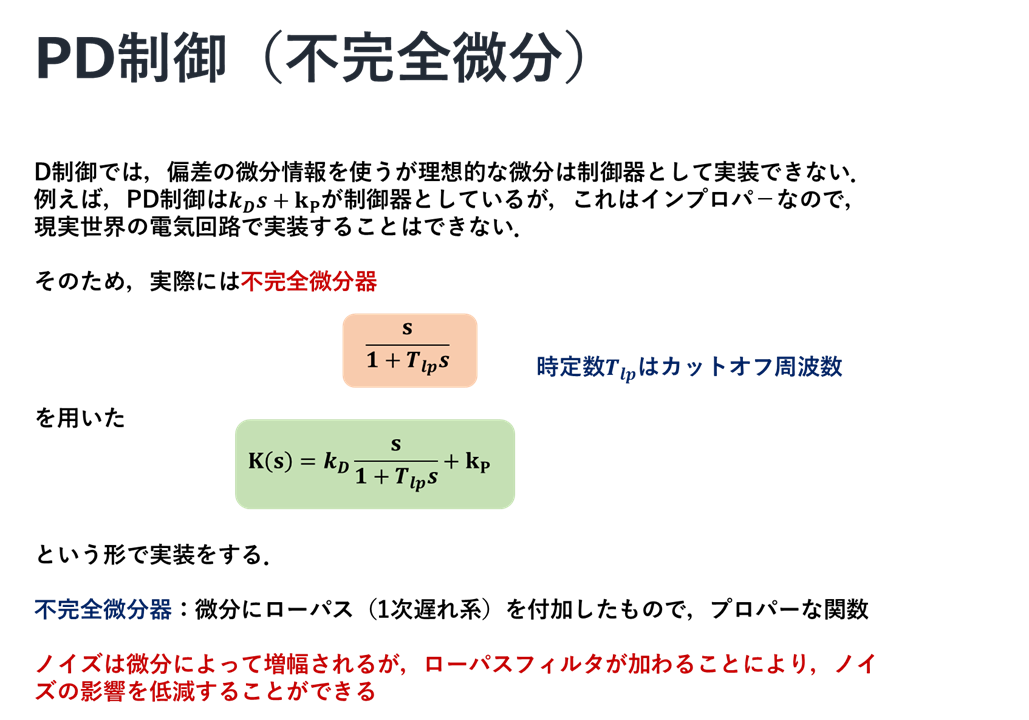
PD制御
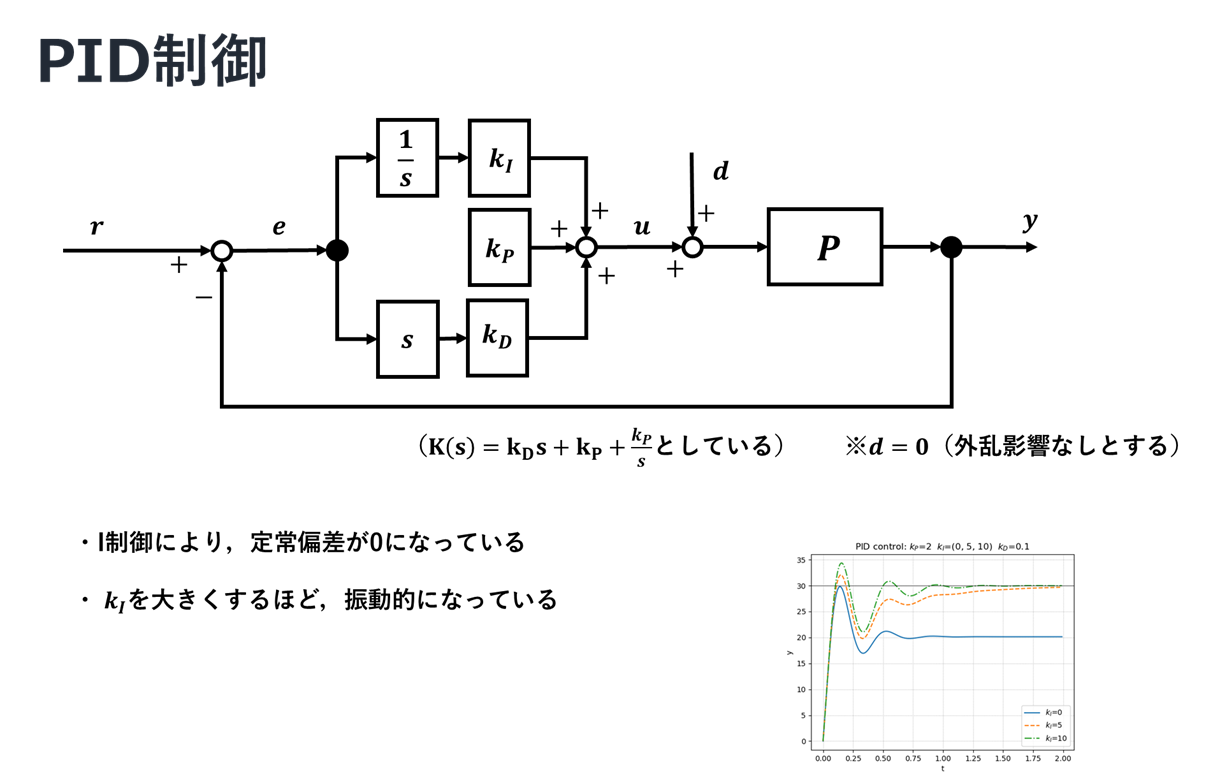
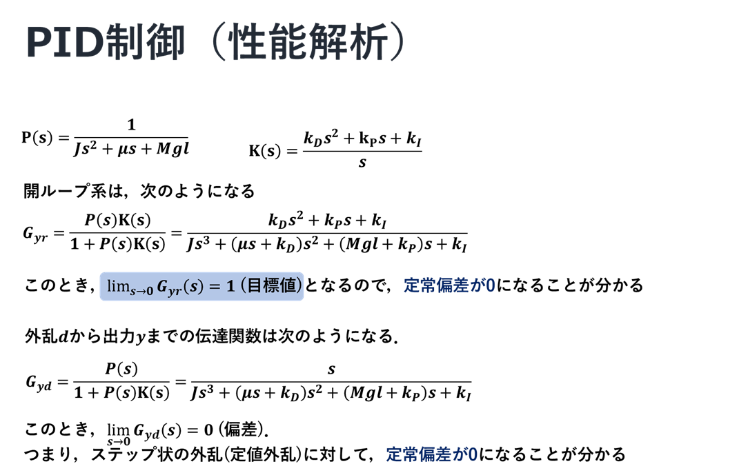
PID制御
実装
先ほどの図の作成を含めて,上で示した制御に関しての実装を行う.以下では,ソースコードとそのときの出力を示す.
P制御
ソースコード
"""
2021/03/11
@Yuya Shimzu

P制御(アーム)
"""
import numpy as np
import matplotlib.pyplot as plt
from control import tf, feedback
from control.matlab import step, bode, logspace
from tf_arm import arm_tf       #自作関数
# https://qiita.com/Yuya-Shimizu/items/c7b69b4dfd63fb8facfa
from for_plot import linestyle_generator, plot_set, bodeplot_set      #自作関数
# https://qiita.com/Yuya-Shimizu/items/f811317d733ee3f45623

## パラメータ設定
g    =   9.8                    #重力加速度[m/s^2]
l     =   0.2                    #アームの長さ[m]
M   =   0.5                     #アームの質量[kg]
mu =   1.5e-2                #粘性摩擦係数[kg*m^2/s]
J    =   1.0e-2                 #慣性モーメント[kg*m^2]

# 制御対象
P = arm_tf(J, mu, M, g, l)

# 目標値(指示値=refference)
ref = 30        #目標角度30[deg]

# 比例ゲイン
kp = (0.5, 1, 2)        #比較のために3つ用意


## P制御を用いたときのステップ応答の描画
LS = linestyle_generator()
fig, ax = plt.subplots()
for i in range(len(kp)):
    K = tf([0, kp[i]], [0, 1])  #P制御
    Gyr = feedback(P*K, 1)  #閉ループ系
    y, t = step(Gyr, np.arange(0, 2, 0.01))     #ステップ応答

    pltargs = {'ls':next(LS), 'label':f"$k_P$={kp[i]}"}
    ax.plot(t, y*ref, **pltargs)

ax.set_title('P control')
ax.axhline(ref, color='k', linewidth=0.5)
plot_set(ax, 't', 'y', 'best')

plt.show()


## P制御を用いたときのボード線図
LS = linestyle_generator()
fig, ax = plt.subplots(2, 1)
for i in range(len(kp)):
    K = tf([0, kp[i]], [0, 1])  #P制御
    Gyr = feedback(P*K, 1)  #閉ループ系
    gain, phase, w = bode(Gyr, logspace(-1, 2), Plot=False)     #ボード線図

    pltargs = {'ls':next(LS), 'label':f"$k_P$={kp[i]}"}
    ax[0].semilogx(w, 20*np.log10(gain), **pltargs)
    ax[1].semilogx(w, phase*180/np.pi, **pltargs)

ax[0].set_title('P control - Bode Plot')
bodeplot_set(ax, 'lower left')

plt.show()
出力
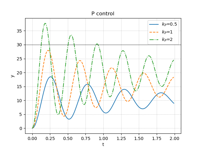
説明にあったように,確かにゲインを高めることで目標値には近づくが目標値になることはなく,さらに振動的になっていることが分かる.
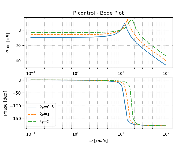
ゲインを高めることで,バンド幅は大きくできているが,ピークゲインも大きくなってしまっていることが分かる.
PD制御
ソースコード
"""
2021/03/11
@Yuya Shimzu

PD制御(アーム)
"""
import numpy as np
import matplotlib.pyplot as plt
from control import tf, feedback
from control.matlab import step, bode, logspace
from tf_arm import arm_tf       #自作関数
# https://qiita.com/Yuya-Shimizu/items/c7b69b4dfd63fb8facfa
from for_plot import linestyle_generator, plot_set, bodeplot_set      #自作関数
# https://qiita.com/Yuya-Shimizu/items/f811317d733ee3f45623

## パラメータ設定
g    =   9.8                    #重力加速度[m/s^2]
l     =   0.2                    #アームの長さ[m]
M   =   0.5                     #アームの質量[kg]
mu =   1.5e-2                #粘性摩擦係数[kg*m^2/s]
J    =   1.0e-2                 #慣性モーメント[kg*m^2]

# 制御対象
P = arm_tf(J, mu, M, g, l)

# 目標値(指示値=refference)
ref = 30        #目標角度30[deg]

# 比例ゲインと微分ゲイン
kp = 2
kd = (0, 0.1, 0.2)        #比較のために3つ用意


## PD制御を用いたときのステップ応答の描画
LS = linestyle_generator()
fig, ax = plt.subplots()
for i in range(len(kd)):
    K = tf([kd[i], kp], [0, 1])  #PD制御
    Gyr = feedback(P*K, 1)  #閉ループ系
    y, t = step(Gyr, np.arange(0, 2, 0.01))     #ステップ応答

    pltargs = {'ls':next(LS), 'label':f"$k_D$={kd[i]}"}
    ax.plot(t, y*ref, **pltargs)

ax.set_title(f"PD control: $k_P$={kp}  $k_D$={kd}")
ax.axhline(ref, color='k', linewidth=0.5)
plot_set(ax, 't', 'y', 'best')

plt.show()


## PD制御を用いたときのボード線図
LS = linestyle_generator()
fig, ax = plt.subplots(2, 1)
for i in range(len(kd)):
    K = tf([kd[i], kp], [0, 1])  #PD制御
    Gyr = feedback(P*K, 1)  #閉ループ系
    gain, phase, w = bode(Gyr, logspace(-1, 2), Plot=False)     #ボード線図

    pltargs = {'ls':next(LS), 'label':f"$k_D$={kd[i]}"}
    ax[0].semilogx(w, 20*np.log10(gain), **pltargs)
    ax[1].semilogx(w, phase*180/np.pi, **pltargs)

ax[0].set_title(f"PD control : $k_P$={kp}  $k_D$={kd} - Bode Plot")
bodeplot_set(ax, 'lower left')

plt.show()
出力
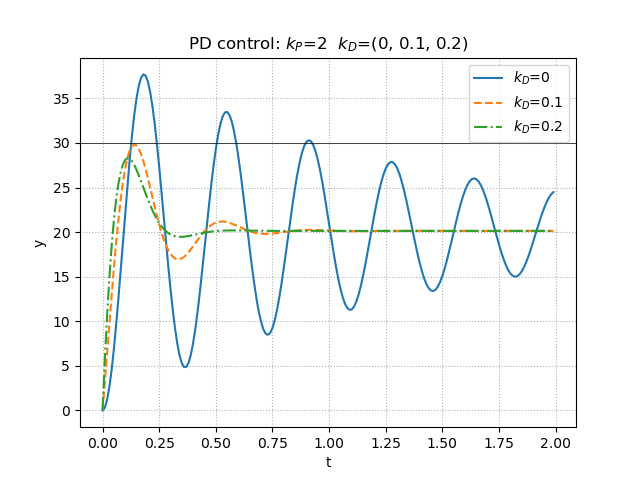
PD制御において,微分ゲインを高めることで,振動が抑えられていることがよくわかる.しかしながら,これでもやはり目標値には到達せず,定常偏差が残ってしまうということも確認できる.
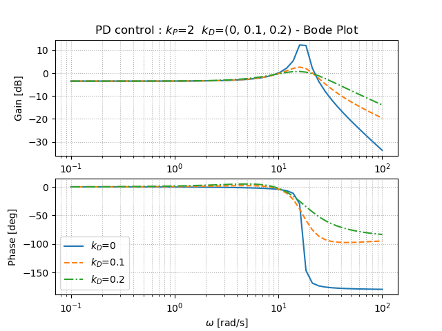
P制御とは異なり,バンド幅を大きくしながらもピークゲインを小さくすることができていることが分かる.
PID制御
ソースコード
"""
2021/03/11
@Yuya Shimzu

PID制御(アーム)
"""
import numpy as np
import matplotlib.pyplot as plt
from control import tf, feedback
from control.matlab import step, bode, logspace
from tf_arm import arm_tf       #自作関数
# https://qiita.com/Yuya-Shimizu/items/c7b69b4dfd63fb8facfa
from for_plot import linestyle_generator, plot_set, bodeplot_set      #自作関数
# https://qiita.com/Yuya-Shimizu/items/f811317d733ee3f45623

## パラメータ設定
g    =   9.8                    #重力加速度[m/s^2]
l     =   0.2                    #アームの長さ[m]
M   =   0.5                     #アームの質量[kg]
mu =   1.5e-2                #粘性摩擦係数[kg*m^2/s]
J    =   1.0e-2                 #慣性モーメント[kg*m^2]

# 制御対象
P = arm_tf(J, mu, M, g, l)

# 目標値(指示値=refference)
ref = 30        #目標角度30[deg]

# 比例ゲインと微分ゲイン
kp = 2
kd = 0.1
ki = (0, 5, 10)        #比較のために3つ用意


## PID制御を用いたときのステップ応答の描画
LS = linestyle_generator()
fig, ax = plt.subplots()
for i in range(len(ki)):
    K = tf([kd, kp, ki[i]], [1, 0])  #PID制御
    Gyr = feedback(P*K, 1)  #閉ループ系
    y, t = step(Gyr, np.arange(0, 2, 0.01))     #ステップ応答

    pltargs = {'ls':next(LS), 'label':f"$k_I$={ki[i]}"}
    ax.plot(t, y*ref, **pltargs)

ax.set_title(f"PID control: $k_P$={kp}  $k_I$={ki}  $k_D$={kd}")
ax.axhline(ref, color='k', linewidth=0.5)
plot_set(ax, 't', 'y', 'best')

plt.show()


## PID制御を用いたときのボード線図
LS = linestyle_generator()
fig, ax = plt.subplots(2, 1)
for i in range(len(ki)):
    K = tf([kd, kp, ki[i]], [1, 0])  #PID制御
    Gyr = feedback(P*K, 1)  #閉ループ系
    gain, phase, w = bode(Gyr, logspace(-1, 2), Plot=False)     #ボード線図

    pltargs = {'ls':next(LS), 'label':f"$k_I$={ki[i]}"}
    ax[0].semilogx(w, 20*np.log10(gain), **pltargs)
    ax[1].semilogx(w, phase*180/np.pi, **pltargs)

ax[0].set_title(f"PID control : $k_P$={kp} $k_I$={ki} $k_D$={kd} - Bode Plot")
bodeplot_set(ax, 'lower left')

plt.show()
出力
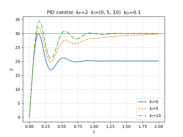
積分ゲインを高めることで振動的にはなるが,しっかりと目標値に向かって収束していく様子が確認できる.
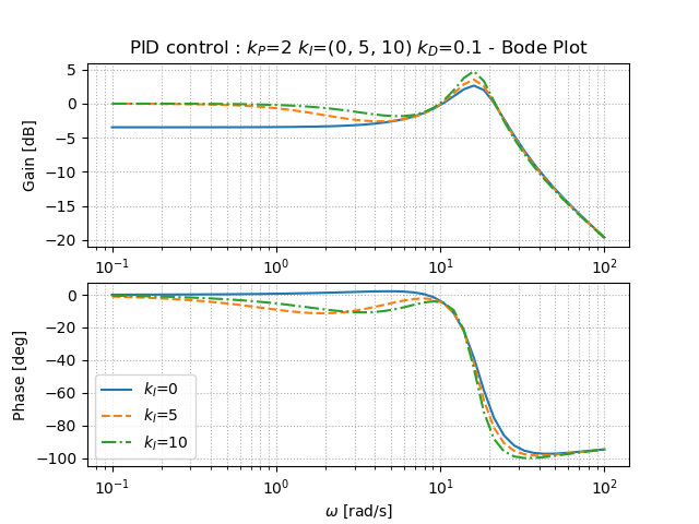
積分ゲインを高めることで,低周波ゲインが0となり,低周波では落ち着いた挙動であることが予想される.ピークゲインは少し高めてしまうが,少し振動的になるという部分でも先ほどの時間応答との図の結果と一致していることが分かる.
PID制御の外乱抑制性能
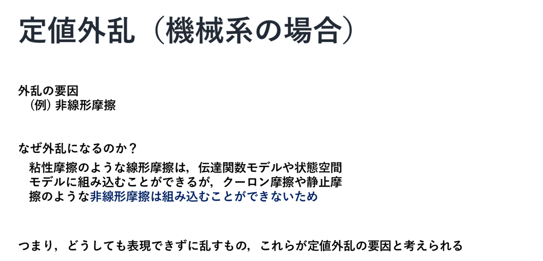
最後にPID制御の外乱抑制性能についての実装も行う.上の説明でもあったように外乱があったときどれほど抑制できるのかということを図から理解する練習ともいえる.プログラムはほとんど変わらず,フィードバック関数を適用する部分で,外乱から出力の式にするだけである.
ソースコード
"""
2021/03/11
@Yuya Shimzu

PID制御 - 外乱抑制性能(アーム)
"""
import numpy as np
import matplotlib.pyplot as plt
from control import tf, feedback
from control.matlab import step, bode, logspace
from tf_arm import arm_tf       #自作関数
# https://qiita.com/Yuya-Shimizu/items/c7b69b4dfd63fb8facfa
from for_plot import linestyle_generator, plot_set, bodeplot_set      #自作関数
# https://qiita.com/Yuya-Shimizu/items/f811317d733ee3f45623

## パラメータ設定
g    =   9.8                    #重力加速度[m/s^2]
l     =   0.2                    #アームの長さ[m]
M   =   0.5                     #アームの質量[kg]
mu =   1.5e-2                #粘性摩擦係数[kg*m^2/s]
J    =   1.0e-2                 #慣性モーメント[kg*m^2]

# 制御対象
P = arm_tf(J, mu, M, g, l)

# 目標値(指示値=refference)
ref = 30        #目標角度30[deg]

# 比例ゲインと微分ゲイン
kp = 2
kd = 0.1
ki = (0, 5, 10)        #比較のために3つ用意


## PID制御を用いたときのステップ応答の描画
LS = linestyle_generator()
fig, ax = plt.subplots()
for i in range(len(ki)):
    K = tf([kd, kp, ki[i]], [1, 0])  #PID制御
    Gyd = feedback(P, K)  #d → y
    y, t = step(Gyd, np.arange(0, 2, 0.01))     #ステップ応答

    pltargs = {'ls':next(LS), 'label':f"$k_I$={ki[i]}"}
    ax.plot(t, y*ref, **pltargs)

ax.set_title(f"PID control - disturbance: $k_P$={kp}  $k_I$={ki}  $k_D$={kd}")
ax.axhline(ref, color='k', linewidth=0.5)
plot_set(ax, 't', 'y', 'best')

plt.show()


## PID制御を用いたときのボード線図
LS = linestyle_generator()
fig, ax = plt.subplots(2, 1)
for i in range(len(ki)):
    K = tf([kd, kp, ki[i]], [1, 0])  #PID制御
    Gyd = feedback(P, K)  #d → y
    gain, phase, w = bode(Gyd, logspace(-1, 2), Plot=False)     #ボード線図

    pltargs = {'ls':next(LS), 'label':f"$k_I$={ki[i]}"}
    ax[0].semilogx(w, 20*np.log10(gain), **pltargs)
    ax[1].semilogx(w, phase*180/np.pi, **pltargs)

ax[0].set_title(f"PID control - disturbance: $k_P$={kp} $k_I$={ki} $k_D$={kd} - Bode Plot")
bodeplot_set(ax, 'lower left')

plt.show()
出力
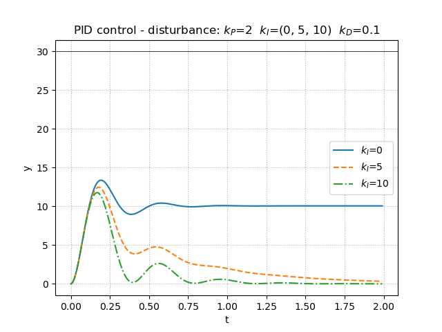
積分ゲインを高めることで,やはり振動的にはなるものの,外乱の影響が0へ近づいて抑制されていることが分かる.
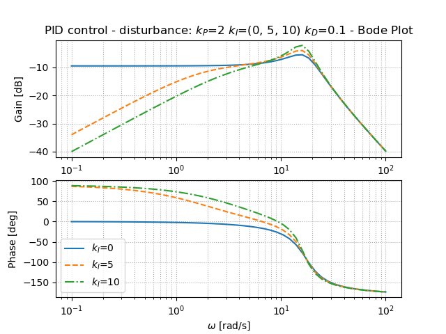
積分ゲインを高めることでピークゲインが大きくなっていることから,ここでも振動的になることが確認できる.さらに,低周波ゲインが大きいということは,低周波において挙動が大きい,つまり外乱に働きかけていると予想される.
感想
改めて,PID制御を少し分解しながら学んだことで,各制御,各ゲインの役割と特徴について知ることができた.また,図から読み取ることはまだ慣れてはいないとは感じたが,なんとなくつかめてきているとは思う.もっというと,時間応答については,直感的に理解しやすいが,周波数応答が少し不安だと感じた.上での図に対する考察も一部間違っているかもしれない.しかしながら,図だけで実機が無くても,ある程度のシミュレーション,挙動の推測ができるというのは,やはり強力だなと思い,よりいっそうボード線図や時間応答の図示の重要性を感じさせられた.
参考文献
Pyhtonによる制御工学入門 南 祐樹 著 オーム社
