0
0

Delete article

Deleted articles cannot be recovered.

Draft of this article would be also deleted.

Are you sure you want to delete this article?

LTSPICEでハイパス、ローパスの回路シミュレーション(ascファイル付き)

Posted at

初めに

とりあえずLTspiceを初めて最初にハイパスとローパスを作れと言われたので、作りました。参考に示すYouTubeを元にしていますので、ぜひ見てください!!

回路設計

以下のような回路を作成します。時定数は全て0.5μsにしています。
スクリーンショット 2025-01-15 14.34.00.png
抵抗はRキー、コンデンサーはCキーで選択、wireは左クリックして、draftのWiresから出してください。

電圧の設定

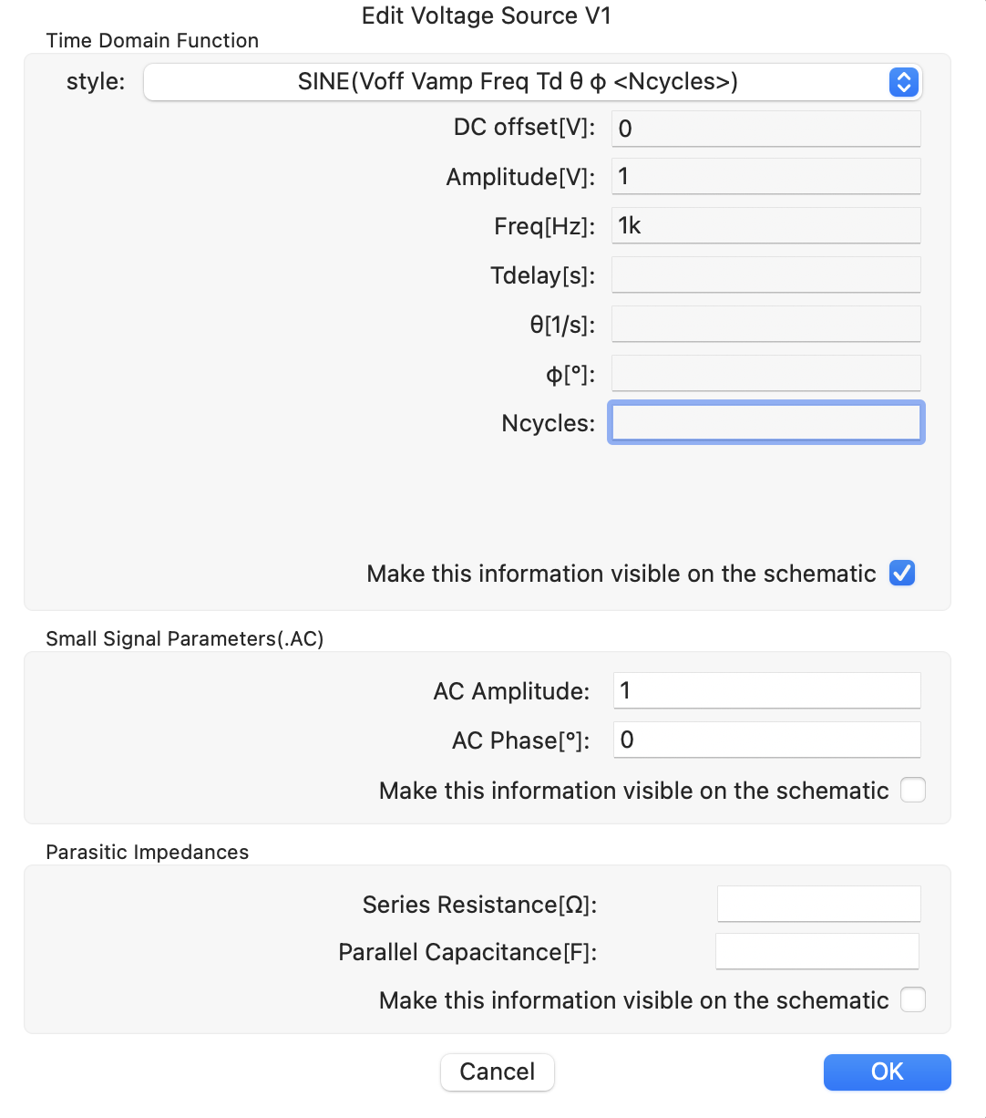
STYLEをSINEに変更し、DCオフセットを0V、AC電源の最大は1Vで周波数を1kにしてください。(周波数はac解析では無視されるので、選択しなくてもok)
スクリーンショット 2025-01-15 14.36.15.png

simulationの設定

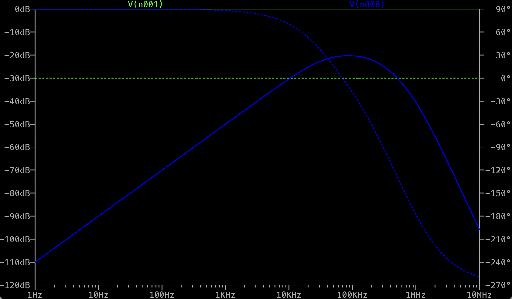
simulationは次のようにAC電源の周波数を1Hzから1MHzで1桁あたり100測定点でシミュレーションします。コマンドは以下です。

LTspice
.ac dec 100 1 10Meg

実行結果

スクリーンショット 2025-01-15 14.44.06.png

ざっくり、緑が入力電圧、青が出力電圧で、実線が電圧の入出力のスケール(dB)、点線が位相差(°)となっています。見るとハイパスとローパスの両方が入っています。

コード

以下のgitにあります。
https://github.com/Y-Watanabe11/HPF1_LPF4

参考

LTSpice Simulation Passive RC component Band Pass Filter Frequency Phase Amplitude
by Circuit Simulations
https://www.youtube.com/watch?v=pU1PaPZndrE
0
0
0

Register as a new user and use Qiita more conveniently

  1. You get articles that match your needs
  2. You can efficiently read back useful information
  3. You can use dark theme
What you can do with signing up
0
0

Delete article

Deleted articles cannot be recovered.

Draft of this article would be also deleted.

Are you sure you want to delete this article?