はじめに
以下のような一軸方向の運動と接触を考慮したボールと平面のモデルを作成しましたので簡単に解説資料を作成します。
斜めから見たアニメーション
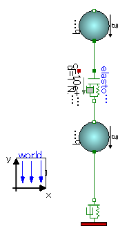
ブロック図は以下です。
Modelicaライブラリ勉強会で「みんなで実験や解析をしたい」という話になり多数決を取ったところ「ピタゴラスイッチに出てくるような装置を作ってみよう」という話になりました。
OpenModelicaでアニメーション機能があるのでグラフィカルに表示できますし、ボールの動き、ギアのモデルや果ては核反応計算ライブラリまであるため面白いピタゴラスイッチが出来そうです。
まずは既存ライブラリの調査、剛体の運動・衝突の実装、アニメーション機能についてモデルを作りながら基礎調査を行いました。
既存ライブラリの調査
ピタゴラスイッチといえば剛体の運動、剛体の運動といえばModelica Standard Library(MSL)のMechanicsパッケージです。
Mechanicsパッケージは以下の3構成となっています。
- Translational : 1軸並進運動
- Rotational : 1軸回転運動
- MultiBody : 6自由度運動
これだけ見るとMultiBodyが最適ですが、MultiBodyには接触の計算機能がありません。
一応、接触を考慮するパッケージが有志によって公開されています。
https://github.com/tbeu/IdealizedContact
しかし、私の環境ではMSLのバージョンを揃えても方程式と未知数の数が一致せずExamplesが解けませんでした。
その他にもMultiBodyはライブラリ構成が難しく方程式数も非常に大きくなかなか解くのも難しそうかなと。
そこで既存ライブラリを使ってピタゴラ装置用のライブラリを作成することにしました。
1軸並進運動とその接触のモデル化
ピタゴラ装置でよく見かけるビー玉が一方向に転がっていく現象は一軸方向のみの運動を考慮すれば計算できそうです。
そこでまず1軸方向の並進運動のみを考慮できる質点の運動と衝突を計算できるモデルを既存ライブラリを使って作成します。
1軸並進運動のモデル化
1軸並進運動のモデル化については、Modelica.Mechanics.Translationalパッケージを使用します。
Translationalパッケージの詳しい仕様などはユーザーガイド(Modelica.Mechanics.Translational.UsersGuide)をご覧ください。
massモデル - 1軸並進運動が定義された既存モデル
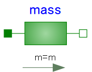
Translationalパッケージ内のMassモデルにはニュートンの運動方程式F=maが定義されています。
方程式部分のみを以下に示します。
equation
  v = der(s);
  a = der(v);
  m*a = flange_a.f + flange_b.f;
v = \frac{ds}{dt} \\
a = \frac{dv}{dt} \\
ma = f_1 + f_2 \\
v : 速度[m/s]  \\
a : 加速度[m/(s^2)] \\
m : 質量[kg]  \\
f : 力[N]  \\
非常にシンプルに二階微分の運動方程式を表しています。
ユーザーは力でも速度でも任意の未知数を定義すれば、あとはソルバが自動的にその他の未知数を求めてくれます。
接触のモデル化
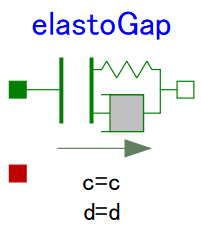
厳密に接触を定義するのは難しいのですが、簡易的な接触モデルなら既存モデルElastGapを使用することで表現できます。
両端の物体が一定距離まで近づくとそれらの物体に反発力と減衰力を作用させます。
ElastGapモデル - 1軸並進運動時の接触に使用出来るモデル
ソースコード 長いので折り畳んでいます
class Modelica.Mechanics.Translational.Components.ElastoGap "1D translational spring damper combination with gap"
  final parameter enumeration(never, avoid, default, prefer, always) stateSelect = StateSelect.prefer "Priority to use s_rel and v_rel as states";
  parameter Real s_nominal(quantity = "Length", unit = "m", min = 0.0) = 0.0001 "Nominal value of s_rel (used for scaling)";
  Real s_rel(quantity = "Length", unit = "m", start = 0.0, nominal = s_nominal, stateSelect = StateSelect.prefer) "Relative distance (= flange_b.s - flange_a.s)";
  Real v_rel(quantity = "Velocity", unit = "m/s", start = 0.0, stateSelect = StateSelect.prefer) "Relative velocity (= der(s_rel))";
  Real f(quantity = "Force", unit = "N") "Forces between flanges (= flange_b.f)";
  Real flange_a.s(quantity = "Length", unit = "m") "Absolute position of flange";
  Real flange_a.f(quantity = "Force", unit = "N") "Cut force directed into flange";
  Real flange_b.s(quantity = "Length", unit = "m") "Absolute position of flange";
  Real flange_b.f(quantity = "Force", unit = "N") "Cut force directed into flange";
  parameter Real c(quantity = "TranslationalSpringConstant", unit = "N/m", min = 0.0, start = 1.0) "Spring constant";
  parameter Real d(quantity = "TranslationalDampingConstant", unit = "N.s/m", min = 0.0, start = 1.0) "Damping constant";
  parameter Real s_rel0(quantity = "Length", unit = "m") = 0.0 "Unstretched spring length";
  parameter Real n(min = 1.0) = 1.0 "Exponent of spring force ( f_c = -c*|s_rel-s_rel0|^n )";
  final parameter Boolean useHeatPort = false "=true, if heatPort is enabled";
  Real lossPower(quantity = "Power", unit = "W") "Loss power leaving component via heatPort (> 0, if heat is flowing out of component)";
  Boolean contact "=true, if contact, otherwise no contact";
  protected Real f_c(quantity = "Force", unit = "N") "Spring force";
  protected Real f_d2(quantity = "Force", unit = "N") "Linear damping force";
  protected Real f_d(quantity = "Force", unit = "N") "Linear damping force which is limited by spring force (|f_d| <= |f_c|)";
equation
  flange_a.f = 0.0;
  flange_b.f = 0.0;
  contact = s_rel < s_rel0;
  f_c = smooth(1, noEvent(if contact then -c * abs(s_rel - s_rel0) ^ n else 0.0));
  f_d2 = if contact then d * v_rel else 0.0;
  f_d = smooth(0, noEvent(
    if contact then
      if f_d2 < f_c then
        f_c
      else if f_d2 > (-f_c) then
        -f_c
      else
        f_d2
    else 0.0));
  f = f_c + f_d;
  lossPower = f_d * v_rel;
  s_rel = flange_b.s - flange_a.s;
  v_rel = der(s_rel);
  flange_b.f = f;
  flange_a.f = -f;
end Modelica.Mechanics.Translational.Components.ElastoGap;
接触は非線形な挙動のため、解の不連続な変化やチャタリングを発生させる原因となるイベントを発生させないようにsmoothオペレータやnoEventオペレータを使用しています。
また非物理的な挙動としないための検討がDocumentに書いてあるのでご覧ください。
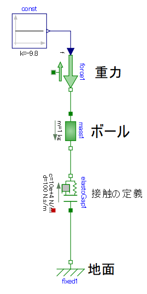
バウンドするボールの例題
massモデルとElastoGapモデルを使って落下して地面に跳ね返るボールの挙動を解析します。
モデルは以下となります。
結果のボールの位置は以下です。
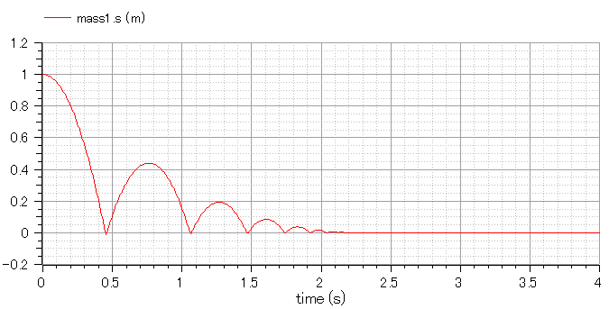
1軸並進運動と接触は計算できそうです。
アニメーション機能
OpenModelicaには3Dアニメーションを表示させる機能がついていて、MSLのアニメーション表示させるためのクラスに適切な設定を行い計算を実行するとアニメーションが表示されます。
OpenModelicaの3Dアニメーション機能
アニメーションが表示可能なモデルに対して以下の「Simulate with Animation」ボタンから計算を実行すると計算結果が3Dアニメーションで表示されます。
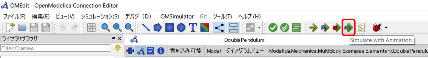
以下はMSLのサンプルの二重振り子を計算した結果画面です。
Modelica.Mechanics.MultiBody.Examples.Elementary.DoublePendulum
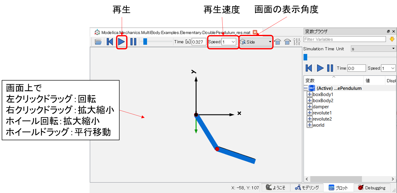
(画像をクリックすると大きな画像で開きます)
Shapeモデル - アニメーション表示を定義するモデル
以下のModelica.Mechanics.MultiBody.Visualizers.Advanced.Shapeモデルに適切な値を入力することでアニメーションが表示されます。
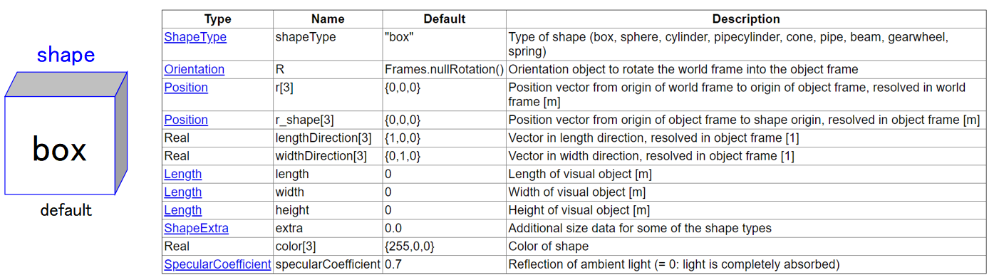
ShapeTypeパラメータ - 物体の形状
ShapeTypeで物体の形状を定義できます。
事前に用意されている形状とDXF形式のCADデータを表示させることができます。
事前に用意されている形状は以下の8個です。
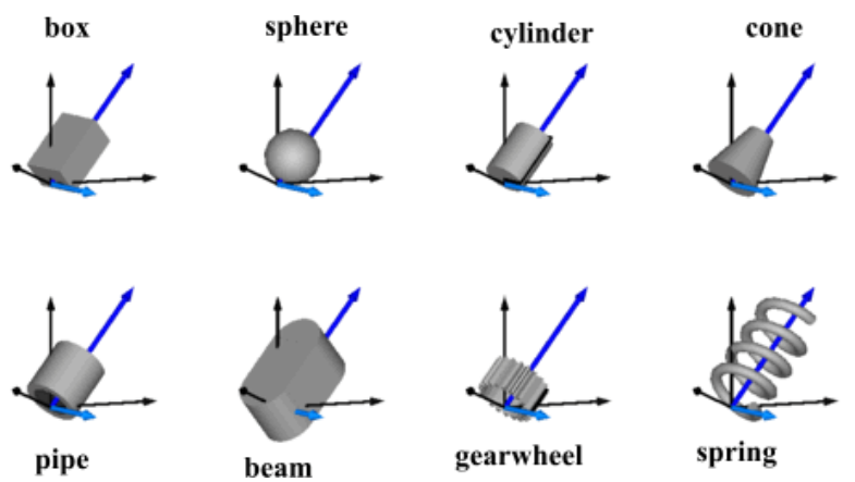
以下のように入力することで反映されます。
- 事前に用意されている形状
shapeType = "box" - DXF形式のCADデータ
shapeType="modelica://Modelica/Resources/Data/Shapes/RobotR3/b0.dxf"
事前に用意されている形状を上手く組み合わせれば複雑な形状も表現できます。
length, width, height, lengthDirection, widthDirectionパラメータ - 物体の寸法
物体の寸法を定義するため以下の縦、横、高さ方向の長さが必要です。
- length ・・・ 縦の長さ
- width ・・・ 横の長さ
- height ・・・ 高さの長さ
そして、どちらが縦方向や横方向は全体座標系でいえばxyz方向のどちらかを以下のパラメータに入力します。
- lengthDirection[3] ・・・ 3次元のベクトル
- widthDirection[3] ・・・ 3次元のベクトル
例.ただの箱の表示
縦2m、横1m、高さ0.1mの箱を表示させてみましょう。
回転や移動はしません。
model sample1

  import Modelica.Mechanics.MultiBody.Frames;
  inner Modelica.Mechanics.MultiBody.World world annotation(
    Placement(visible = true, transformation(origin = {-74, -30}, extent = {{-10, -10}, {10, 10}}, rotation = 0)));
  Modelica.Mechanics.MultiBody.Visualizers.Advanced.Shape box(
    shapeType = "box",
    length = 2,
    width = 1,
    height = 0.3,
    lengthDirection = {1, 0, 0},
    widthDirection = {0, 0, 1},
    r_shape = {0, 0, 0},
    r = {0, 0, 0},
    R = Frames.nullRotation());

end sample1;
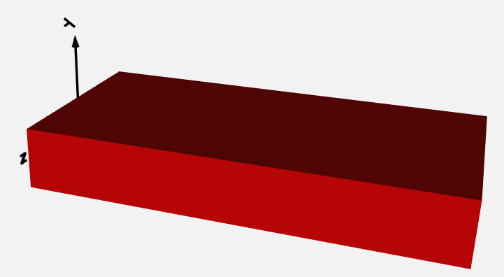
ただの箱を表示させることができました。
r,r_shapeパラメータ - 物体のxyz座標位置、並進運動
物体の形状と寸法を定義できたので次は物体の位置を定義しましょう。
以下のパラメータで定義できます。
r[3] ・・・ 全体座標系の中での物体原点の座標位置
r_shape[3] ・・・ rからオフセットさせる物体原点の座標位置
物体は左端が全体座標系の原点になるようです。
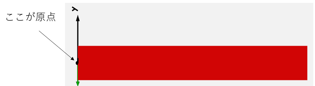
箱の重心を全体座標系の原点に移動させたい場合は、r_shapeに重心位置(のマイナス)を入れてあげましょう。
物体の並進移動はrに時刻に応じた値を入れてみましょう。
例. 箱の並進移動
時刻に比例してx方向に並進移動する箱を作ってみます。
rにtimeが入っていることに着目してください。
model sample2

  import Modelica.Mechanics.MultiBody.Frames;
  inner Modelica.Mechanics.MultiBody.World world annotation(
    Placement(visible = true, transformation(origin = {-74, -30}, extent = {{-10, -10}, {10, 10}}, rotation = 0)));
  Modelica.Mechanics.MultiBody.Visualizers.Advanced.Shape box(
    shapeType = "box",
    length = 2,
    width = 1,
    height = 0.3,
    lengthDirection = {1, 0, 0},
    widthDirection = {0, 0, 1},
    r_shape = {0, 0, 0},
    r = {time, 0, 0},
    R = Frames.nullRotation());

end sample2;
Rパラメータ - 物体の回転運動
Rは物体の回転運動を定義するパラメータです。
RはModelica.Mechanics.MultiBody.Frames.Orientationのインスタンスです。
Modelica.Mechanics.MultiBody.Frames.Orientationのクラス図もどきを書いてみました。
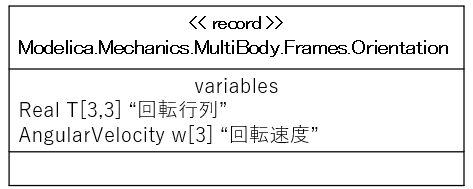
詳細な解説は以下です。
https://build.openmodelica.org/Documentation/Modelica.Mechanics.MultiBody.Frames.Orientation.html
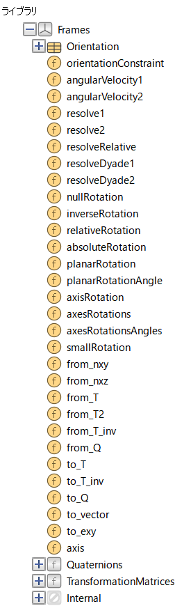
Orientationクラスでは、Rに直接値を入力することは絶対に止めてModelica.Mechanics.MultiBody.Frames内のFunctionを使うようにとの注意書きがあります。
Frams内のFunctionは沢山あって自分のやりたいことに応じて選ぶ必要があります。
例.箱の回転
x軸周りに1secに1回転する箱です。
model sample3
  import Modelica.Mechanics.MultiBody.Frames;
  inner Modelica.Mechanics.MultiBody.World world annotation(
    Placement(visible = true, transformation(origin = {-74, -30}, extent = {{-10, -10}, {10, 10}}, rotation = 0)));
  Frames.Orientation R;
  Modelica.Mechanics.MultiBody.Visualizers.Advanced.Shape box(
    shapeType = "box",
    length = 2,
    width = 1,
    height = 0.3,
    lengthDirection = {1, 0, 0},
    widthDirection = {0, 0, 1},
    r_shape = {0, 0, 0},
    r = {0, 0, 0},
    R = R);
equation
  R = Frames.axisRotation(1,time*3.14,der(time*3.14));
end sample3;
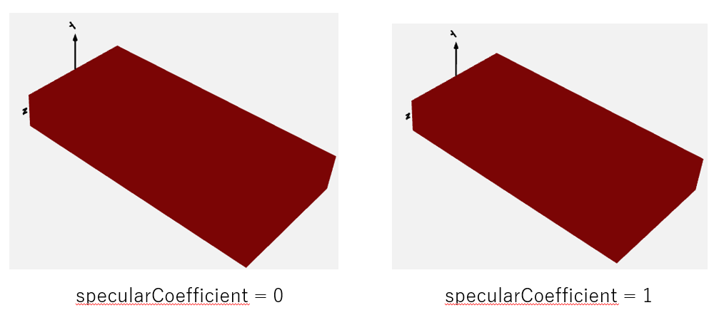
color, specularCoefficientパラメータ - 色や光の吸収率
color ・・・ RGB値で定義されます。
specularCoefficient ・・・ 物体表面が光を吸収する比率です。0だと完全吸収です。
ただOpenModelica1.14だとspecularCoefficientは差がよく分かりません。
一軸方向の運動と接触を考慮したボールと平面のモデル
執筆中です。