概要
前回はM5StickCを使用して赤外線データ受信機を作りました。そこで、今回はそのデータを使用してESP32から同じ赤外線データを送信する「送信機」を作ります。
実際の写真:
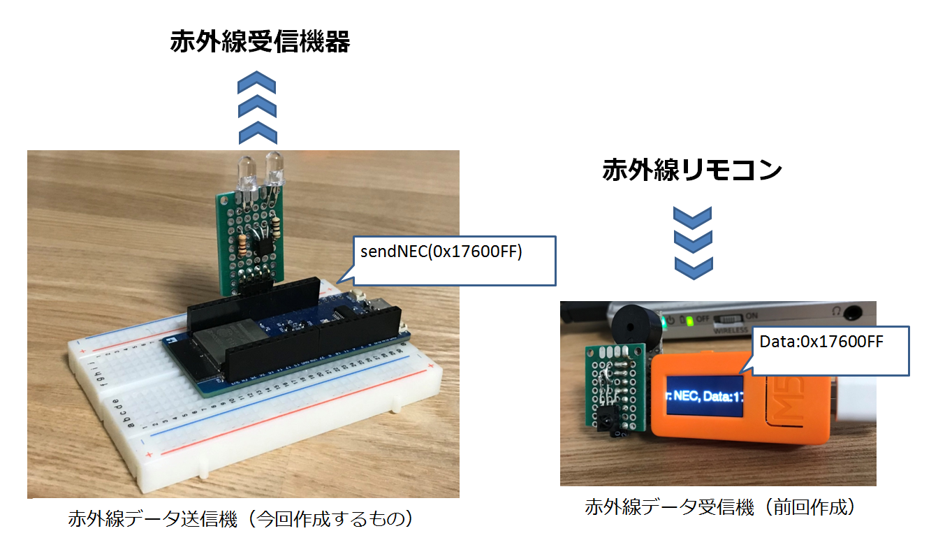
※サポートしている赤外線データはNEC方式のみです
※ESP32のソフトはESP-IDFを使って作ります
使用したもの
- ESPr® Developer 32
- ESP-IDF (xtensa-esp32-elf at the 1.22.0-80)
- 開発に使用したOS:Ubuntu18.04 ( Windows7 Pro 64bit をホストOSとするVirtualBoxにインストール )
- 5mm赤外線LED
- トランジスタ 2SC1815GR
- 抵抗(100Ω、10Ω)
結線
以下の図のように結線して送信機を作りました。
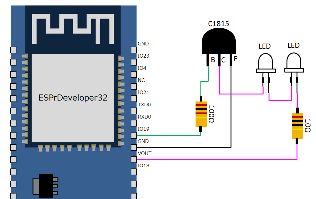
※LEDのアノード(+:長い足の方)とカソード(ー:短い足の方)を逆にしないように注意すること
※赤外線の出力を強くしたい場合は赤外線LEDをESP32とは別電源にすると良いと思います(参考記事→「光の強化」)
ソースコード
ソースコードは下の「rct_example.c」の通りです。ライブラリは追加しないでhelloworldプログラムのメインファイルを変更して作りました。
ソースコード全体
// ESP IDF ESP32 remote ctrol transmitter Example

#include <stdio.h>
#include <string.h>
#include "freertos/FreeRTOS.h"
#include "freertos/task.h"
#include "freertos/queue.h"
#include "freertos/semphr.h"
#include "esp_err.h"
#include "esp_log.h"
#include "driver/rmt.h"


static const char* LOG_TAG = "TEST_LOG";

static const uint32_t LIGHT_ON = 0x017611EE;
static const uint32_t LIGHT_OFF = 0x017600FF;

const rmt_channel_t RMT_CHANNEL = RMT_CHANNEL_0;
const gpio_num_t IR_PIN = GPIO_NUM_19;
const int  RMT_TX_CARRIER_EN = 1;   // Enable carrier for IR transmitter test with IR led

const int leaderOnUs = 9000;
const int leaderOffUs = 4500;
const int dataOnUs = 560;
const int data1OffUs = 1690;
const int data0OffUs = 560;
const int stopbitOnUs = 560;
const int stopbitOffUs = 0x7fff;

// send NEC format remote control data
void sendNECRCData(uint32_t sendCode) {
  const int sendDataLength = 34;        // NEC format data length 34 bit
  rmt_item32_t sendData[sendDataLength]; // data to send
  uint16_t customCode = (uint16_t)((sendCode>>16) & 0x0000FFFF) ;
  uint8_t dataCode = (uint8_t)(((sendCode & 0x0000FF00)>>8) & 0x000000FF) ;

  // Leader code
  sendData[0].duration0 = leaderOnUs;
  sendData[0].level0 = 1;
  sendData[0].duration1 = leaderOffUs;
  sendData[0].level1 = 0;

  //Customer Code
  for (int i = 0; i < 2; i++) {
    for (int j = 0; j < 8; j++) {
      sendData[8 * i + j + 1].duration0 = dataOnUs;
      sendData[8 * i + j + 1].level0 = 1;
      if (customCode & (1 << ((1-i) * 8 + (7-j)))) {
        // 1: ON 560us + OFF 1690us
        sendData[8 * i + j + 1].duration1 = data1OffUs;
      } else {
        // 0: ON 560us + OFF  560us
        sendData[8 * i + j + 1].duration1 = data0OffUs;
      }
      sendData[8 * i + j + 1].level1 = 0;
    }
  }


  // Data code
  for (int i = 0; i < 8; i++) {
    sendData[i + 17].duration0 = dataOnUs;
    sendData[i + 25].duration0 = dataOnUs;
    sendData[i + 17].level0 = 1;
    sendData[i + 25].level0 = 1;
    if (dataCode & (1 << (7-i))) {
      sendData[i + 17].duration1 = data1OffUs;
      sendData[i + 25].duration1 = data0OffUs;
    } else {
      sendData[i + 17].duration1 = data0OffUs;
      sendData[i + 25].duration1 = data1OffUs;
    }
    sendData[i + 17].level1 = 0;
    sendData[i + 25].level1 = 0;
  }

  /* stop bit 1bit: ON 560 */
  sendData[33].duration0 = stopbitOnUs;
  sendData[33].level0 = 1;
  sendData[33].duration1 = stopbitOffUs;
  sendData[33].level1 = 0;

  rmt_write_items(RMT_CHANNEL, sendData, sendDataLength, true);
  rmt_wait_tx_done(RMT_CHANNEL, portMAX_DELAY); // wait tx (no limit)

}

void setup_rmt_config() {
  // put your setup code here, to run once:
  rmt_config_t rmtConfig;

  rmtConfig.rmt_mode = RMT_MODE_TX;  // transmit mode
  rmtConfig.channel = RMT_CHANNEL;  // channel to use 0 - 7
  rmtConfig.clk_div = 80;  // clock divider 1 - 255. source clock is 80MHz -> 80MHz/80 = 1MHz -> 1 tick = 1 us
  rmtConfig.gpio_num = IR_PIN; // pin to use
  rmtConfig.mem_block_num = 1; // memory block size

  rmtConfig.tx_config.loop_en = 0; // no loop
  rmtConfig.tx_config.carrier_freq_hz = 38000;  // IR remote controller uses 38kHz carrier frequency
  rmtConfig.tx_config.carrier_duty_percent = 33; // duty
  rmtConfig.tx_config.carrier_level =  RMT_CARRIER_LEVEL_HIGH; // carrier level
  rmtConfig.tx_config.carrier_en = RMT_TX_CARRIER_EN;  // carrier enable
  rmtConfig.tx_config.idle_level =  RMT_IDLE_LEVEL_LOW ; // signal level at idle
  rmtConfig.tx_config.idle_output_en = true;  // output if idle

  rmt_config(&rmtConfig);
  rmt_driver_install(rmtConfig.channel, 0, 0);
}

static void rmt_example_nec_tx_task()
{
    vTaskDelay(10);
    setup_rmt_config();
    esp_log_level_set(LOG_TAG, ESP_LOG_INFO);
    uint32_t send_data = LIGHT_ON;

    while(1) {
      ESP_LOGI(LOG_TAG, "SEND RMT DATA");

      sendNECRCData(send_data);
      if(send_data == LIGHT_ON) {
        send_data = LIGHT_OFF;
      }
      else {
        send_data = LIGHT_ON;
      }

      vTaskDelay(10000 / portTICK_PERIOD_MS); //10 sec delay

    }

    vTaskDelete(NULL);
}

void app_main()
{
    xTaskCreate(rmt_example_nec_tx_task, "rmt_nec_tx_task", 2048, NULL, 10, NULL);
}
関数の概要
- app_main:メイン処理(rmt_example_nec_tx_taskのタスクを起動するのみ)
- rmt_example_nec_tx_task:送信間隔10秒でライトON(0x017611EE)とライトOFF(0x017600FF)のデータを繰り返し赤外線送信する
- setup_rmt_config:赤外線送信のための初期化処理
- sendNECRCData:赤外線送信を行う
ソースコードのざっくり解説
(1):赤外線データ受信機で取得した赤外線リモコンのデータ(LIGHT_ON:照明オン、LIGHT_OFF:照明オフ)
(2):赤外線LEDの制御用端子としてIO19を使用する
(3):10秒の間を空けて照明オンとオフの赤外線データ送信を交互に繰り返す
 :
static const uint32_t LIGHT_ON = 0x017611EE; //・・・(1)
static const uint32_t LIGHT_OFF = 0x017600FF;
 :
const gpio_num_t IR_PIN = GPIO_NUM_19; //・・・(2)
 :

static void rmt_example_nec_tx_task()
{
   :
    while(1) {
      ESP_LOGI(LOG_TAG, "SEND RMT DATA");

      sendNECRCData(send_data); //・・・(3)
      if(send_data == LIGHT_ON) {
        send_data = LIGHT_OFF; //・・・(3)
      }
      else {
        send_data = LIGHT_ON; //・・・(3)
      }

      vTaskDelay(10000 / portTICK_PERIOD_MS); //10 sec delay

    }

   :

}
注意事項
※参考記事と同じエンコード方法だとバイトオーダー・ビットオーダーが逆になっていたので変更しています。ひょっとしたら別の環境では赤外線の送信データが正しく作れない可能性があります。(デコード方法かコンパイラなどの違いか、はたまた他の要因か、全く分かっていません。)
※制御端子の基準クロックとして80MHzとしています。(コードの「rmtConfig.clk_div = 80; 」の部分)一応、オシロでクロックの周期は確認していますが、デフォルトから関連する設定を変えていたりすると、変更する必要があるかもしれません。
終わりに
これで赤外線リモコンを使う色々な機器を制御できそうなので、これからが楽しみです。
今回は、思ったよりもESP-IDFの関連情報が少なかったため、いくつかの場面で少し苦労しました。(特に回路をどうするかなど)
そして、「まさか、オシロを使って目視で赤外線データをデコードしなきゃいけないのか・・・」という場面もありましたが、そこを前回作った受信機が活用できたことは、とても大きなポイントでした。(自分が作ったものに助けられるというのはなかなか良いものです。)
あと、最初は出力が安定しなかったため、トランジスタを入れたら安定したりと色々とレベルアップになったのでとても良い経験になりました。
それでは、見ていただいてありがとうございました。
тнайк чoμ_〆(・ω・。)
参考記事
- RMT(Arduinoで遊ぶページ)
- https://garretlab.web.fc2.com/arduino/esp32/lab/rmt/index.html
- 赤外線リモコンの通信フォーマット
- http://elm-chan.org/docs/ir_format.html
- espressifの赤外線データ送信サンプルコード
- https://github.com/espressif/esp-idf/blob/master/examples/peripherals/rmt_nec_tx_rx/main/infrared_nec_main.c
- Max Power 赤外線LEDキット(スイッチサイエンス) ※回路の参考にさせていただきました
- https://www.switch-science.com/catalog/666/
- Slack から Windows, ESP-WROOM-32 を経由して自宅のエアコンをつける ※Arduinoの開発環境です
- https://qiita.com/cexen/items/5f9e7b28fe1ba4be1f50
- ESP32で赤外線学習リモコンを作る ※Arduinoの開発環境です
- https://qiita.com/td2sk/items/4c0ef83bcc7e74e5e8d5
更新履歴
- 2019-07-31:新規作成