はじめに
C#のWPF3Dを使ってテクスチャを貼り付けたモデルを表示しようとしたときに嵌まった点について記載します。用意したテクスチャ画像の(画像端を含まない)一部をポリゴンに貼り付けようとしたときに、期待したテクスチャ画像の領域が使われないケースがありました。
結論
想定:WPF3DのTextureCoordinatesには画像全体を[0-1]とみなした座標系の座標を指定することで、画像内の任意の領域をテクスチャとしてポリゴンに貼り付けることができる。
問題:画像の内側の一部をテクスチャとして貼り付けたい場合、期待したテクスチャとは異なる範囲が貼り付けられる
結果:WPF3DはTextureCoordinatesに含まれる座標群のMinMaxを[0-1]に正規化して、使用するテクスチャ領域を求めているような挙動を確認した。ダミーの座標を与えることで、期待した領域をテクスチャとして貼り付けることができた。
サンプルコードの説明
サンプルコードは以下の3つのステップについて書かれています。
- テクスチャ画像の左下、右下、左上を三角ポリゴンに貼り付ける。テクスチャ座標は画像端を利用する。
- テクスチャ画像の右下、右上、左上を三角ポリゴンに貼り付ける。テクスチャ座標は画像端を含まない内側の領域を指定する。失敗例。
- (2)に対策を施した成功例
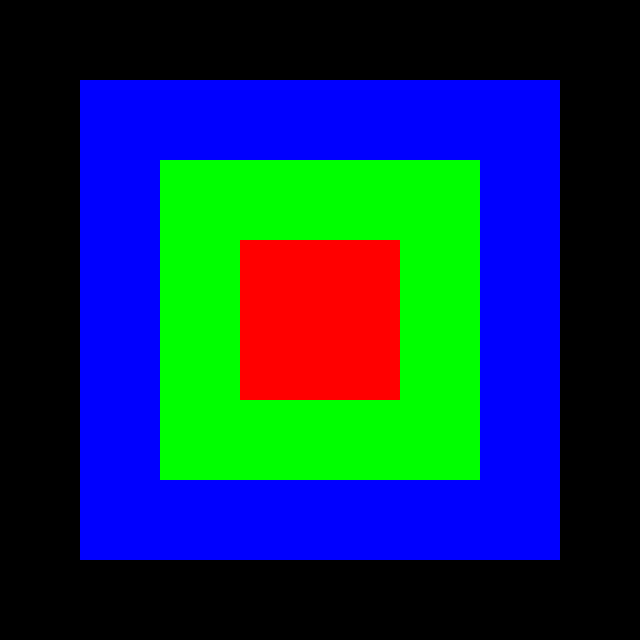
次のような画像を使ってテクスチャとしてポリゴンに貼り付けていきます。外側から黒、青、緑、赤の四角で構築された画像です。
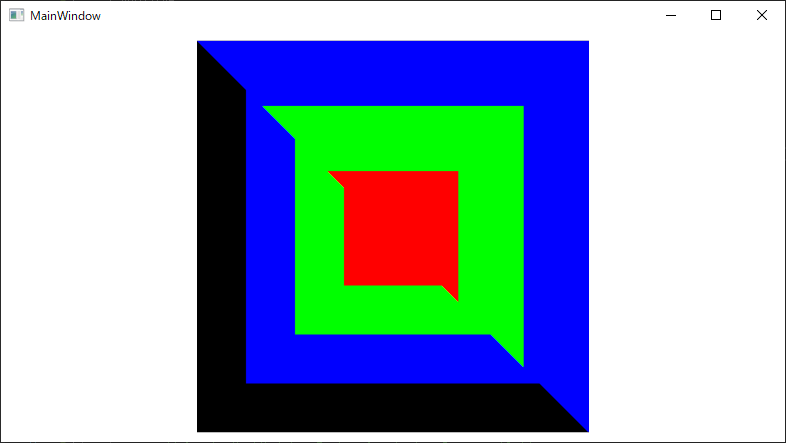
成功した場合、以下のようなモデルが表示されます。
サンプルコードのリポジトリは以下になります。WPF3DTextureTestという名前のプロジェクトを作成しています。
動作環境
Visual Studio 2019
WPF
.NET Core 3.1
サンプルコードその1(テクスチャ座標は画像端を利用するケース)
画像の左下、右下、左上を三角ポリゴンに貼り付けます。
<Window x:Class="WPF3DTextureTest.MainWindow"
        xmlns="http://schemas.microsoft.com/winfx/2006/xaml/presentation"
        xmlns:x="http://schemas.microsoft.com/winfx/2006/xaml"
        xmlns:d="http://schemas.microsoft.com/expression/blend/2008"
        xmlns:mc="http://schemas.openxmlformats.org/markup-compatibility/2006"
        mc:Ignorable="d"
        Title="MainWindow" Height="450" Width="800">
    <Viewport3D x:Name="Viewport"/>
</Window>
public MainWindow()
{
    InitializeComponent();

    // Camera Setting
    var camera = new OrthographicCamera();
    camera.Position = new Point3D(0, 0, 1);
    camera.LookDirection = new Vector3D(0, 0, -1);
    camera.UpDirection = new Vector3D(0, 1, 0);

    this.Viewport.Camera = camera;

    // Light Setting
    var light = new DirectionalLight(Colors.White, new Vector3D(0, 0, -1));
    var lightVisual = new ModelVisual3D();
    lightVisual.Content = light;

    this.Viewport.Children.Add(lightVisual);

    // TextureImage Setting
    int width = 640;
    int height = 640;

    Mat<Vec3b> colorImage = new Mat<Vec3b>(height, width, new Scalar(0, 0, 0));
    Cv2.Rectangle(colorImage, new OpenCvSharp.Rect(width * 1 / 8, height * 1 / 8, width * 3 / 4, height * 3 / 4), new Scalar(255, 0, 0), thickness: -1);
    Cv2.Rectangle(colorImage, new OpenCvSharp.Rect(width * 2 / 8, height * 2 / 8, width * 2 / 4, height * 2 / 4), new Scalar(0, 255, 0), thickness: -1);
    Cv2.Rectangle(colorImage, new OpenCvSharp.Rect(width * 3 / 8, height * 3 / 8, width * 1 / 4, height * 1 / 4), new Scalar(0, 0, 255), thickness: -1);

    // Create MeshModel - TextureCoorinates Range : [0-1]
    {
        var mesh = new MeshGeometry3D();

        mesh.Positions.Add(new Point3D(-0.5, -0.5, 0));
        mesh.Positions.Add(new Point3D(0.5, -0.5, 0));
        mesh.Positions.Add(new Point3D(-0.5, 0.5, 0));

        mesh.Normals.Add(new Vector3D(0, 0, 1));
        mesh.Normals.Add(new Vector3D(0, 0, 1));
        mesh.Normals.Add(new Vector3D(0, 0, 1));

        mesh.TextureCoordinates.Add(new System.Windows.Point(0.0, 1.0));
        mesh.TextureCoordinates.Add(new System.Windows.Point(1.0, 1.0));
        mesh.TextureCoordinates.Add(new System.Windows.Point(0.0, 0.0));

        mesh.TriangleIndices.Add(0);
        mesh.TriangleIndices.Add(1);
        mesh.TriangleIndices.Add(2);

        var bitmapSource = BitmapSourceConverter.ToBitmapSource(colorImage);
        var imageBrush = new ImageBrush(bitmapSource);

        var material = new DiffuseMaterial(imageBrush);

        var geometry = new GeometryModel3D(mesh, material);

        var modelVisual = new ModelVisual3D();
        modelVisual.Content = geometry;

        this.Viewport.Children.Add(modelVisual);
    }
}
コードを実行すると以下のような画面が表示されます。期待したように動作します。
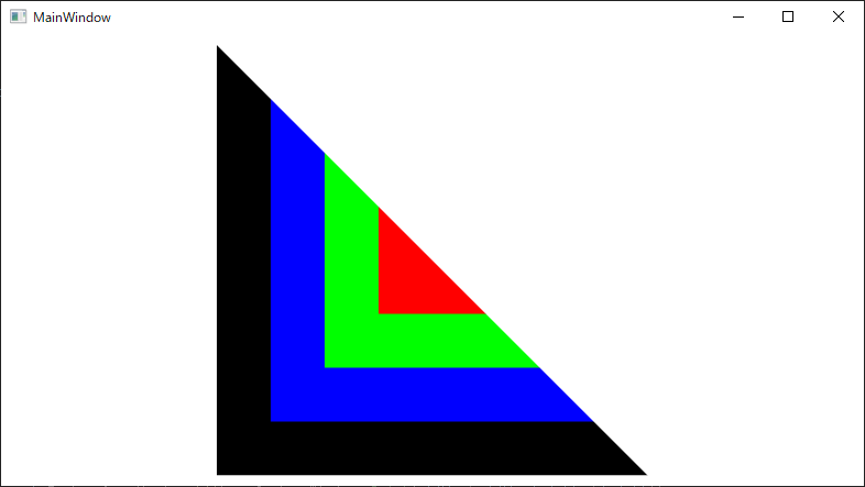
サンプルコードその2(テクスチャ座標は画像端を含まない内側の領域を指定するケース、失敗例)
画像の右下、右上、左上を三角ポリゴンに貼り付けます。今度はテクスチャとして使う範囲を黒ではなく青にするためにTextureCoordinatesに入れる値を[0-1]から[1/8-7/8]に変更します。
public MainWindow()
{
    InitializeComponent();

    ...

    // Create MeshModel - TextureCoorinates Range : [0-1]
    {
        ...
    }

    // Create MeshModel - TextureCoorinates Range : [1/8-7/8]
    {
        var mesh = new MeshGeometry3D();

        mesh.Positions.Add(new Point3D(0.5, -0.5, 0));
        mesh.Positions.Add(new Point3D(0.5, 0.5, 0));
        mesh.Positions.Add(new Point3D(-0.5, 0.5, 0));

        mesh.Normals.Add(new Vector3D(0, 0, 1));
        mesh.Normals.Add(new Vector3D(0, 0, 1));
        mesh.Normals.Add(new Vector3D(0, 0, 1));

        mesh.TextureCoordinates.Add(new System.Windows.Point(7.0 / 8.0, 7.0 / 8.0));
        mesh.TextureCoordinates.Add(new System.Windows.Point(7.0 / 8.0, 1.0 / 8.0));
        mesh.TextureCoordinates.Add(new System.Windows.Point(1.0 / 8.0, 1.0 / 8.0));

        mesh.TriangleIndices.Add(0);
        mesh.TriangleIndices.Add(1);
        mesh.TriangleIndices.Add(2);

        var bitmapSource = BitmapSourceConverter.ToBitmapSource(colorImage);
        var imageBrush = new ImageBrush(bitmapSource);

        var material = new DiffuseMaterial(imageBrush);

        var geometry = new GeometryModel3D(mesh, material);

        var modelVisual = new ModelVisual3D();
        modelVisual.Content = geometry;

        this.Viewport.Children.Add(modelVisual);
    }
}
コードを実行すると以下のような画面が表示されます。右下、右上、左上の三角は青から始まるようにしたかったのですが、サンプルコードその1の時と同じように黒から始まるテクスチャが貼られています。
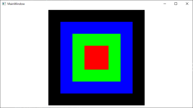
サンプルコードその3(テクスチャ座標は画像端を含まない内側の領域を指定するケース、成功例)
サンプルコードその2の挙動から、TextureCoordinatesに含まれる座標は[0-1]に正規化されて使用されているように思います。そのため、テクスチャ画像の内側の一部を使って貼り付けたい場合、ポリゴンと紐づかないダミーの点群を登録し、TextureCoordinatesに(0, 0)と(1, 1)の座標を与えて正規化の影響を受けないようにします。
public MainWindow()
{
    InitializeComponent();

    ...

    // Create MeshModel - TextureCoorinates Range : [0-1]
    {
        ...
    }

    // Create MeshModel - TextureCoorinates Range : [1/8-7/8]
    {
        var mesh = new MeshGeometry3D();

        mesh.Positions.Add(new Point3D(0.5, -0.5, 0));
        mesh.Positions.Add(new Point3D(0.5, 0.5, 0));
        mesh.Positions.Add(new Point3D(-0.5, 0.5, 0));

        mesh.Normals.Add(new Vector3D(0, 0, 1));
        mesh.Normals.Add(new Vector3D(0, 0, 1));
        mesh.Normals.Add(new Vector3D(0, 0, 1));

        mesh.TextureCoordinates.Add(new System.Windows.Point(7.0 / 8.0, 7.0 / 8.0));
        mesh.TextureCoordinates.Add(new System.Windows.Point(7.0 / 8.0, 1.0 / 8.0));
        mesh.TextureCoordinates.Add(new System.Windows.Point(1.0 / 8.0, 1.0 / 8.0));

        mesh.TriangleIndices.Add(0);
        mesh.TriangleIndices.Add(1);
        mesh.TriangleIndices.Add(2);

        // Set Dummy TextureCoordinates - Range [0-1]
        {
            mesh.Positions.Add(default(Point3D));
            mesh.Positions.Add(default(Point3D));

            mesh.Normals.Add(default(Vector3D));
            mesh.Normals.Add(default(Vector3D));

            mesh.TextureCoordinates.Add(new System.Windows.Point(0, 0));
            mesh.TextureCoordinates.Add(new System.Windows.Point(1, 1));
        }

        var bitmapSource = BitmapSourceConverter.ToBitmapSource(colorImage);
        var imageBrush = new ImageBrush(bitmapSource);

        var material = new DiffuseMaterial(imageBrush);

        var geometry = new GeometryModel3D(mesh, material);

        var modelVisual = new ModelVisual3D();
        modelVisual.Content = geometry;

        this.Viewport.Children.Add(modelVisual);
    }
}
コードを実行すると以下のような画面が表示されます。右下、右上、左上の三角は青から始まるテクスチャが貼られており、期待したように動作します。
おまけ
TextureCoordinatesに入力された座標のMinMaxが[0-1]に正規化されるのであれば、TextureCoordinatesに入力する座標は元のテクスチャ画像の座標でも問題なさそうです。例えば、サンプルコードその1を以下のように書き換えても動作しました。
        // mesh.TextureCoordinates.Add(new System.Windows.Point(0.0, 1.0));
        // mesh.TextureCoordinates.Add(new System.Windows.Point(1.0, 1.0));
        // mesh.TextureCoordinates.Add(new System.Windows.Point(0.0, 0.0));

        mesh.TextureCoordinates.Add(new System.Windows.Point(0.0, height));
        mesh.TextureCoordinates.Add(new System.Windows.Point(width, height));
        mesh.TextureCoordinates.Add(new System.Windows.Point(0.0, 0.0));