Float計算回路のVerilog実装
~ FPGA に載せたい ~
オレオレ実装なので間違っていても知りません
加算回路編
Float計算回路のVerilog-HDL実装について -その1
デバッグツール作成編
Float計算回路の(ry-その1.1(float値の16進数表記)
補足とLeadingZeros編
Float計算回路のVerilog-HDL実装について -その1.5 (LeadingZeros)
減算回路編
Float計算回路のVerilog-HDL実装について -その2(減算編)
目的
floatの勉強
float32のハードウェア実装
その1で作成した加算回路とその2で作成した減算回路を共通化するため、
加算回路(のタイミングなどを)を調整する。
仕様はその1に準拠
仕様
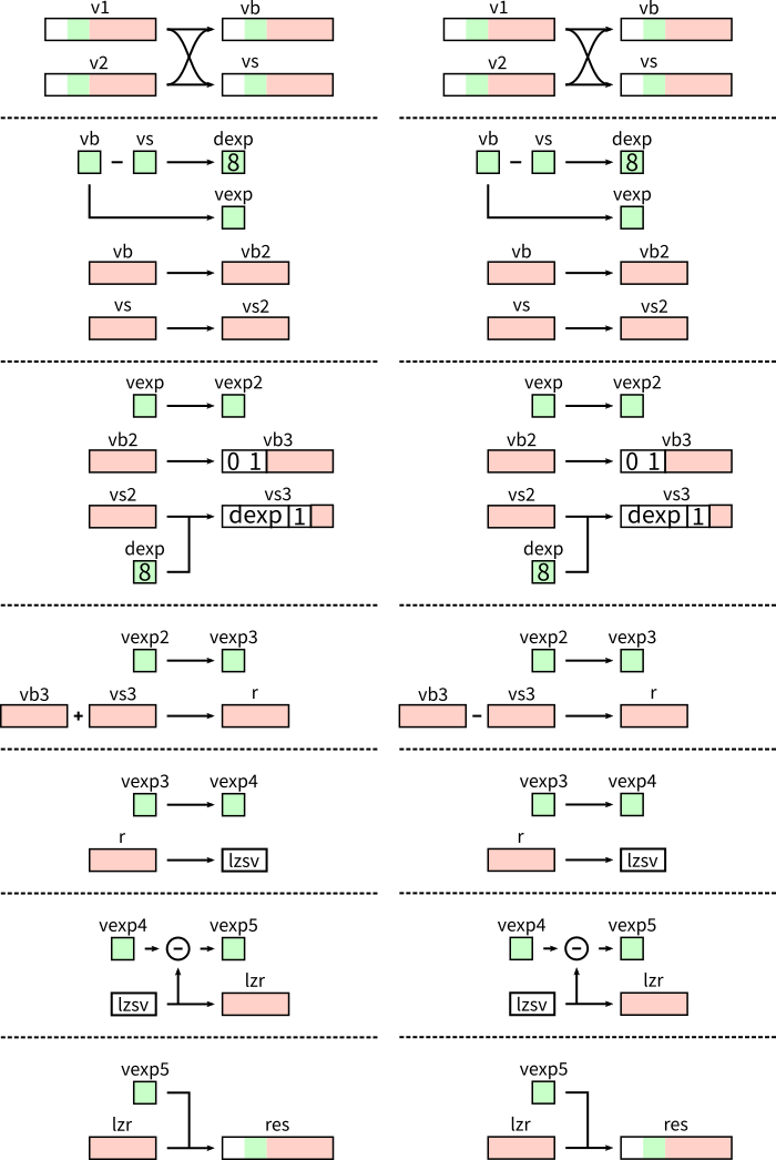
下図右が前回作成した減算回路
下図左が今回作成した加算回路
4クロック目の符号のみ異なる
略コード
float_add2.sv
module float_add(
	input wire clk,
	input wire [31:0] v1,
	input wire [31:0] v2,

	output wire [31:0] vres
);

	assign vres = res;

	//TIM1
	reg [31:0] vb;
	reg [31:0] vs;

	//TIM2
	reg [7:0] dexp;
	reg [7:0] vexp;
	reg [22:0] vb2;
	reg [22:0] vs2;

	//TIM3
	reg [7:0] vexp2;
	reg [24:0] vb3;
	reg [24:0] vs3;

	//TIM4
	reg [7:0] vexp3;
	reg [24:0] r;

	//TIM5,6
	reg [7:0] vexp4;
	reg [7:0] vexp5;
	reg [23:0] lzr;
	wire [7:0] lznum;
	wire [23:0] lzres;

	lzsv lzm(
		.clk(clk),
		.v(r),
		.num(lznum),
		.res(lzres)
	);

	//TIM7
	reg [31:0] res;

	always @(posedge clk) begin

		// TIM1 //
		if (v2[30:23] < v1[30:23]) begin
			vb <= v1;
			vs <= v2;
		end else if (v1[30:23] < v2[30:23]) begin
			vb <= v2;
			vs <= v1;
		end else if (v2[22:0] < v1[22:0]) begin
			vb <= v1;
			vs <= v2;
		end else begin
			vb <= v2;
			vs <= v1;
		end

		// TIM2 //
		dexp <= vb[30:23] - vs[30:23];
		vexp <= vb[30:23];

		vb2 <= vb;
		vs2 <= vs;

		// TIM3 //
		vexp2 <= vexp;

		vb3 <= {2'b1, vb2};
		vs3 <= {1'b0, vssf({1'b1, vs2}, dexp)};

		// TIM4 //
		vexp3 <= vexp2;

		r <= vb3 + vs3;
    //	r <= vb3 - vs3;

		// TIM5 //
		vexp4 <= vexp3;
		vexp5 <= vexp4 - lznum;

		lzr <= lzres;

		// TIM6 //
		res[31] <= 1'b0;
		res[30:23] <= vexp5;
		res[22:0] <= lzr[22:0];

	end

//Value Small Shift Function
function [23:0] vssf(input [23:0] v, input [7:0] num);
(略)
endfunction

endmodule
TIM4 のコメントアウトを逆にすることで、減算できることも確認できている
新しい LeadingZeros 用モジュール
加算回路でもLeadingZerosモジュールを使用するため、
桁下がりだけでなく、桁上がりにもこのLeadingZerosモジュールを対応させる必要がある
leadingzeros2.sv
module lzsv(
	input wire clk,
	input wire [24:0] v,

	output wire [7:0] num,
	output wire [23:0] res
);

// {num8, res24}
 reg [31:0] cnum;
 assign num = cnum[31:24];
 assign res = cnum[23:0];

always @(posedge clk) begin
	if (v[24]) cnum <= {8'hFF, v[24:1]};
	else if (v[23]) cnum <= {8'd0, v[23:0]};
	else if (v[22]) cnum <= {8'd1, v[22:0],  1'b0};
	else if (v[21]) cnum <= {8'd2, v[21:0],  2'b0};
	else if (v[20]) cnum <= {8'd3, v[20:0],  3'b0};
	else if (v[19]) cnum <= {8'd4, v[19:0],  4'b0};

    (略)

	else if (v[ 1]) cnum <= {8'd22, v[ 1:0], 22'b0};
	else if (v[ 0]) cnum <= {8'd23, 24'h800_000};
	else cnum <= {8'd24, 24'd0};
end

endmodule
桁計算時に-1を引くように仕向けるべく 24bit 目が 1 のとき FF(-1) を返す
シミュレーション結果
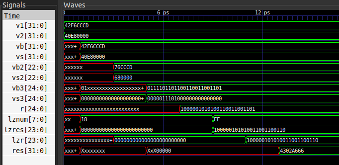
123.4 + 7.25 = 130.65\\
=> 42F6\_CCCD + 40E8\_0000 = 4302\_A666
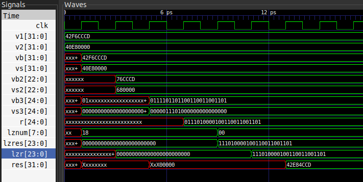
123.4 - 7.25 = 116.15\\
=> 42F6\_CCCD - 40E8\_0000 = 42E8\_4CCD