はじめに
本記事ではXilinx社のソフトコアCPUであるMicroBlazeでFreeRTOSを動作させ、PCのターミナルソフトとFPGAとの間でシリアル通信してI2CやSPI、UARTのペリフェラル制御を行います。
※因みに私はRTOSを触るのは初めてなので、突っ込みどころがありましたらぜひご指南ください。。
設計の背景
FPGAの利用価値は
- 汎用品では不可能な柔軟な回路構成(静的にも動的にも)
- プリミティブな回路による圧倒的なリアルタイム性能
の2点に集約されると言えます。
例えば、数多くのセンサとアクチュエータをぶら下げて、流れてくるデータを監視しながらリアルタイムにデバイス制御したい場合など。
最近ではARMコアと論理回路部がワンパッケージになったFPGAも一般的になってきましたが、ARM上のLinuxにさせるまでもない瑣末な処理で、なおかつリアルタイム性能も重視したい時に便利なのが論理回路側に構成できるソフトコアのCPUです。FPGAベンダーごとに、Xilinx社のMicroBlaze、Intel(旧Altera)社のNiosⅡという無償のCPUが有名です。これらのCPU上でベアメタルでソフトを作ってもいいのですが、ちょっと入り組んだ処理や割込み、エラー処理が入ってくるとなにかと面倒になってきますので、Real-Time OSを導入して楽したいなぁというのが本記事の設計に至った動機です。特に今回利用したFreeRTOS (発音は ふりーあーるとす) は2017年にAmazonに買収されてMITライセンスになりましたので、今後使える場面が多くなるのではと思います。
PCのシリアルコンソールからポチポチとコマンドを送信して各種デバイスが制御できると便利ですので、まずはシリアル通信のコンソールアプリを作ってみました。作業工数は8人日ぐらい。公式のサンプルコードだけでは情報不足で色々とハマりました。
開発環境
- OS: Windows10
- Xilinx ViVado 2018.3
- Xilinx SDK 2018.3
- 特殊電子回路さんのArtix-7開発基板 (いつも使いやすくてお世話になってます)
- Xilinx Platform Cable USBⅡ
FPGAのロジック設計
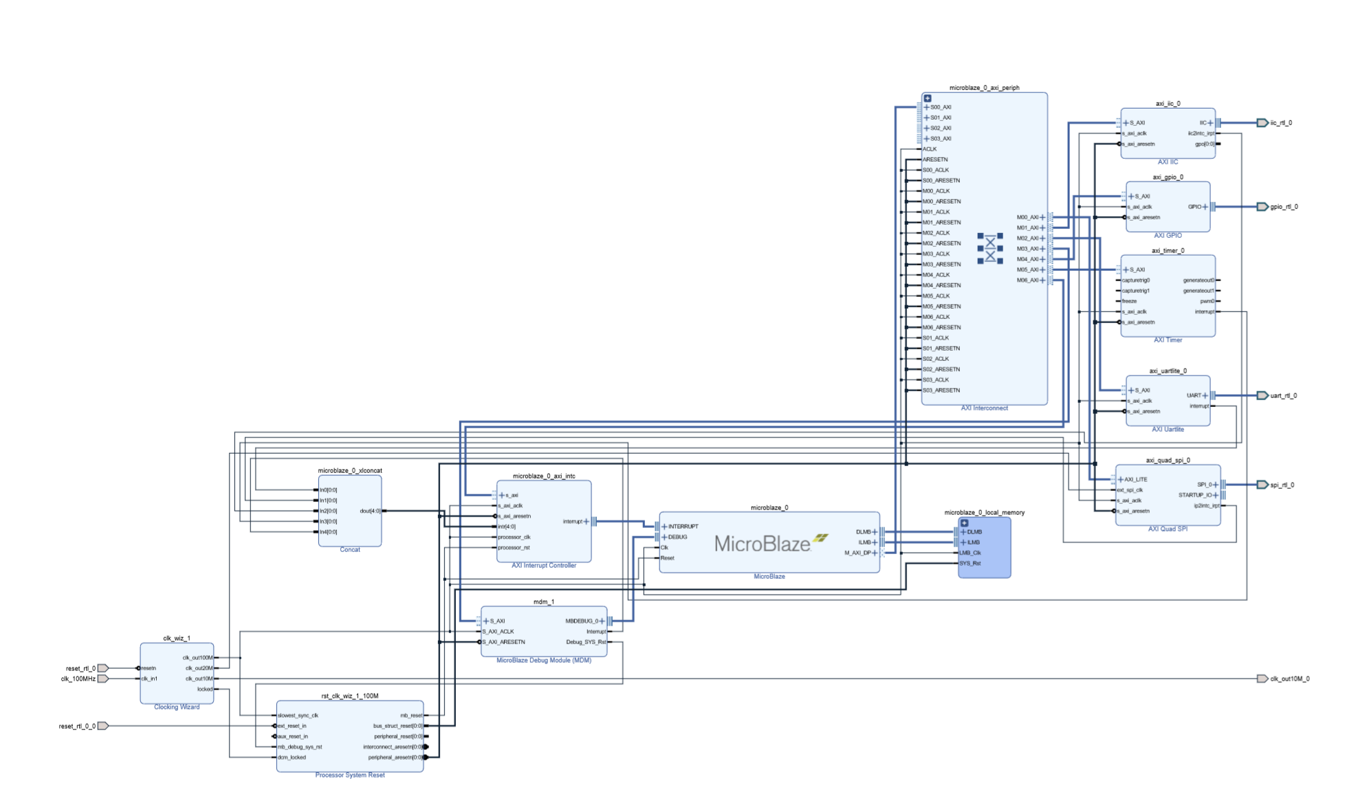
Vivadoのブロックデザインを使ってGUIでちゃちゃっと作りましょう。先人の皆様のZynqの記事も多いので、ここは省略します。できた回路構成は以下図を参考に。GPIOはすべてOutput設定にして基板上の8個のLEDに繋げています。
注意点は下記の通りです。
- FreeRTOSは結構コードサイズが大きい(初期状態でも90K Byteぐらいある)のでMicroBlazeのBlock RAMメモリは128K byteは確保しておくこと(将来的にはDDR3上で動かしたい)
- 各ペリフェラルデバイスの割込み信号出力をMicroBlazeに繋いでおくこと
- ソフトのデバッグ用に標準入出力にSDKのターミナルが使えると便利なので、MicroBlaze Debug Module(MDM)をデザインに入れておくこと
- RTOSを動かすためにタイマーが必須なのでデザインに加えておくこと
Block DesignのWrapperを生成してSynthesis、 Implement、ビットストリーム生成を正常に完了できたら、 File>Expot>Export Hardwareでビットストリームを含むハードウェアデザインファイル(.hdf)を出力してSDKを起動しましょう。
MicroBlazeのソフト設計
Board Support Packageの生成とFreeRTOSのLibrary導入
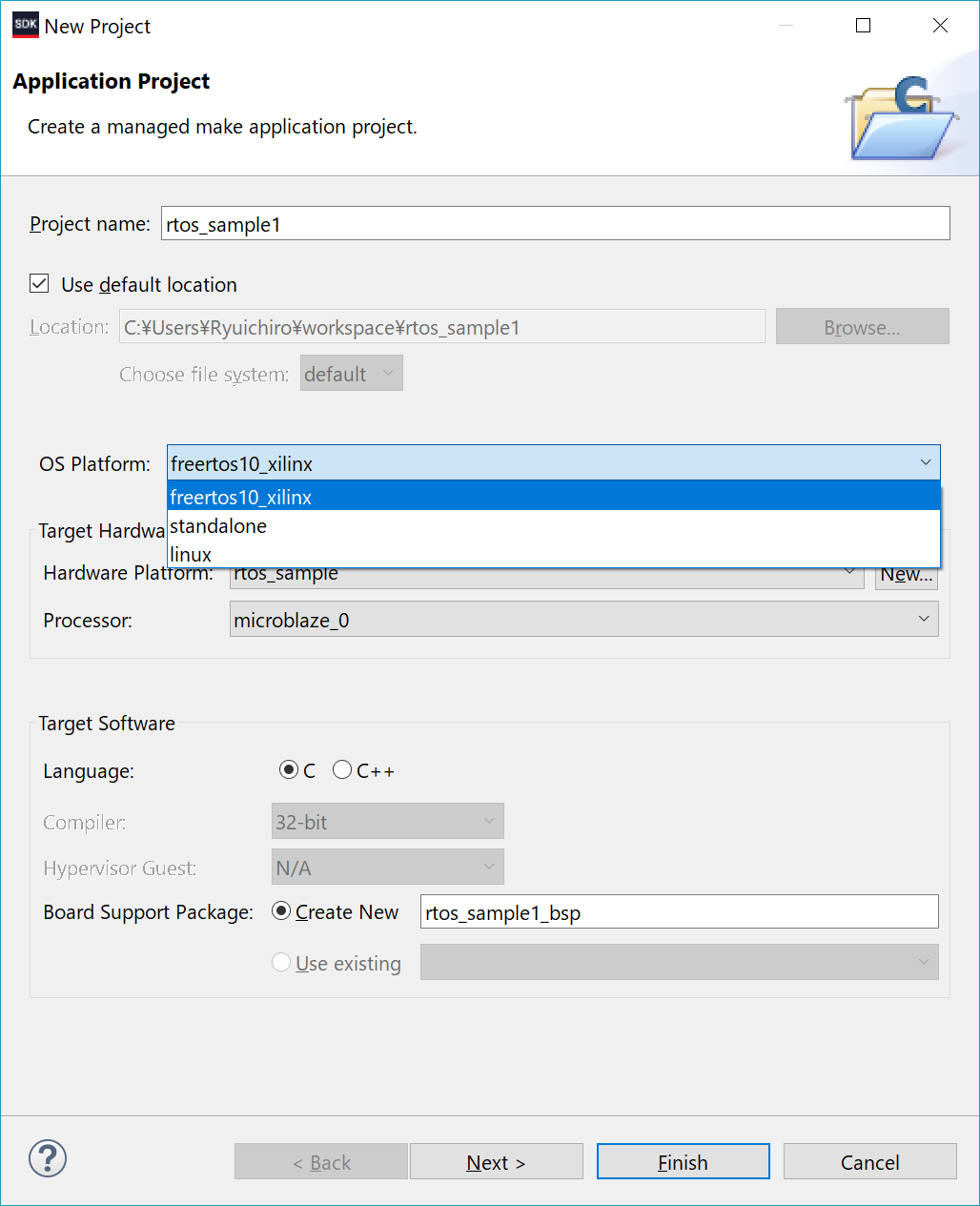
File>New>Application Projectで、先程Vivadoで生成した.hdfからBoard Support PackageをつくりFreeRTOSのライブラリを導入します。OS Platformでfreertos10_xilinxが選べます。FreeRTOSのKernel ver.はv10.0.0でちょっと古いです。Target Hardwareは.hdfファイルと名称を指定すれば出来上がります。

デバッグ環境の設定
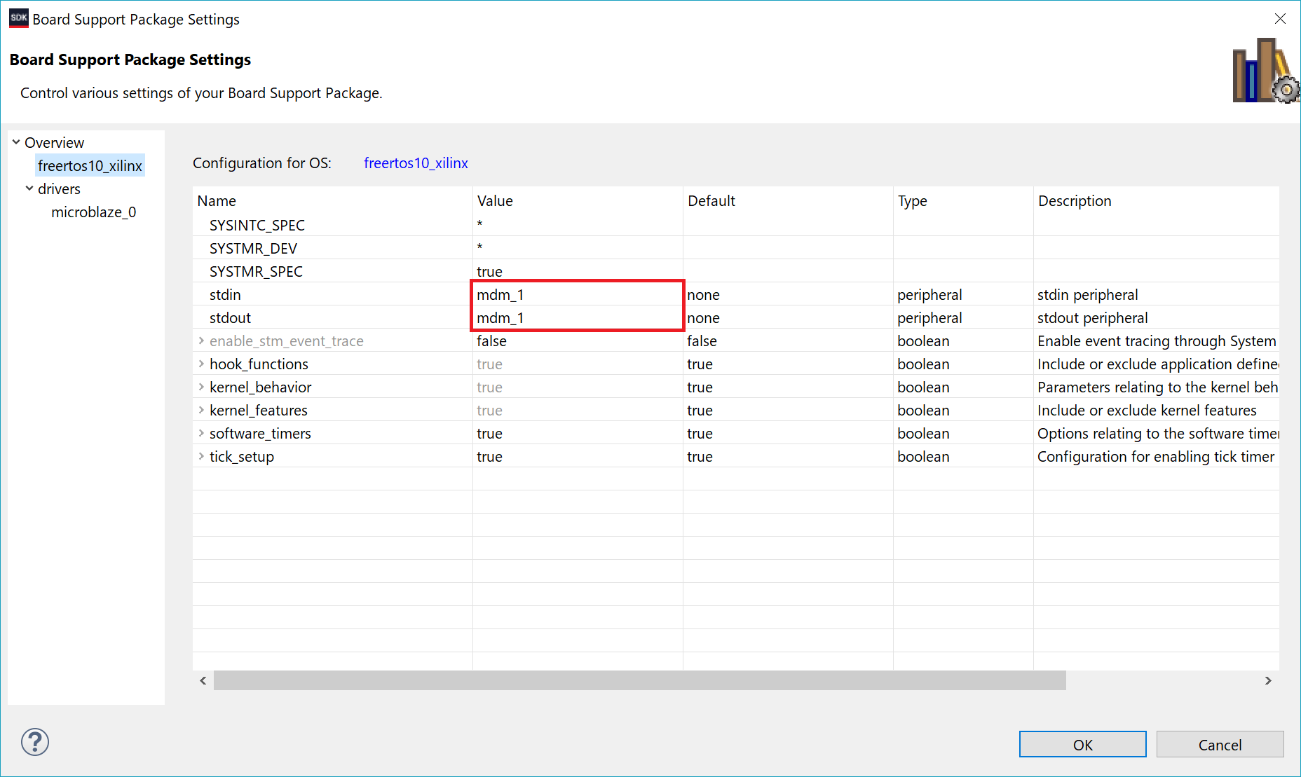
stdin/stdoutにMicroBlaze Debug Module(MDM)を設定することでSDKのターミナルを標準入出力として使えます。デバッグが捗ります。画面左側のProject ExploreにあるBSPを右クリックして"Board Support Package Setting"を開いて設定を変更します。下記の図の赤枠のところ。おそらく初期設定はUartLite IPの名称になっているはずなので、ここをMDMに変更しておきましょう。

これでデバッガ起動後にxil_printf()関数の出力先がSDKのTerminal Consoleになります。標準入力を使いたい場合はSDKのXSCT Consoleを起動して"jtagterminal -start"を実行します。
FreeRTOSのソフト設計
シリアルの送受信にstream_bufferを利用しますが、既存のライブラリにはヘッダファイルしか含まれていませんのでSource Forgeからダウンロードしてstream_buffer.cをProjectにImportして下さい。Kernelのバージョンはv10.0.0で揃えておきましょう。(私はうっかり間違えて最新のv10.1.1のファイルを入れてしまい、色々とハマりました…当然だわ…)
諸々のプロトタイプ宣言は下記のような感じで。
/* Prototype of tasks */
static void prvSetupHardwareTask( void *pvParameters );
static void prvHeartbeatLedTask( void *pvParameters );
static void prvSerialResponseTask( void *pvParameters );
static void prvSerialSendTask( void *pvParameters );

/* Task Handlers */
static TaskHandle_t xSetupHardwareTask;
static TaskHandle_t xLedTask;
static TaskHandle_t xSerialResponseTask;
static TaskHandle_t xSerialSendTask;


/* Stream Buffer Handlers */
static StreamBufferHandle_t xSerialRecvBuffer = NULL;
static StreamBufferHandle_t xSerialSendBuffer = NULL;
static StreamBufferHandle_t xCmdParseBuffer = NULL;

static XUartLite xUartLiteInstance;	/* The instance of the UartLite Device */
static XGpio xGpioOutputInstance;	/* The Instance of the GPIO Driver */

/* Interrupt Service Routine */
static void vSerialRecvISR( void *pvUnused, UBaseType_t uxByteCount );

static volatile UBaseType_t TotalReceivedCount = 0;
メインは以下の通り。RTOSのタスクは4つです。シリアル通信の送受信タスク間のデータのやりとりには、1 write/ 1 readであればスレッドセーフなStream Bufferを大いに利用します。
- ハードウェア初期化 (最優先タスクにして設定完了後に削除)
- LEDの点滅 (動作確認用のHeartBeat)
- シリアル送信
- シリアル受信
int main( void )
{
	xil_printf( "FreeRTOS Console Start\r" );

	xTaskCreate(	prvHeartbeatLedTask, 		/* The function that implements the task. */
					( const char * ) "Led", 	/* Text name for the task, provided to assist debugging only. */
					configMINIMAL_STACK_SIZE, 	/* The stack allocated to the task. */
					NULL, 						/* The task parameter is not used, so set to NULL. */
					tskIDLE_PRIORITY,			/* The task runs at the idle priority. */
					&xLedTask );

	xTaskCreate(	prvSerialResponseTask,
					( const char * ) "SerialResponse",
					configMINIMAL_STACK_SIZE,
					NULL,
					tskIDLE_PRIORITY,
					&xSerialResponseTask );

	xTaskCreate(	prvSerialSendTask,
					( const char * ) "SerialSend",
					configMINIMAL_STACK_SIZE,
					NULL,
					tskIDLE_PRIORITY,
					&xSerialSendTask  );

	xTaskCreate(	prvSetupHardwareTask,
					( const char * ) "Setup",
					configMINIMAL_STACK_SIZE,
					NULL,
					tskIDLE_PRIORITY + 1,
					&xSetupHardwareTask );

	/* Stream buffer for serial Tx & Rx  */
	xSerialRecvBuffer = xStreamBufferCreate( SERIAL_RECV_BUFFER_LENGTH_BYTES, SERIAL_RECV_BUFFER_TRIGGER_LEVEL_1 );
	xSerialSendBuffer = xStreamBufferCreate( SERIAL_SEND_BUFFER_LENGTH_BYTES, SERIAL_SEND_BUFFER_TRIGGER_LEVEL_1 );

	/* Stream buffer for parsing console command */
	xCmdParseBuffer = xStreamBufferCreate( CMD_PARSE_BUFFER_LENGTH_BYTES, CMD_PARSE_BUFFER_TRIGGER_LEVEL_1 );

	/* Start the tasks and timer running. */
	vTaskStartScheduler();

	/* -------------------------------------------------------------------------*/

	/* If all is well, the scheduler will now be running, and the following line
	will never be reached.  If the following line does execute, then there was
	insufficient FreeRTOS heap memory available for the idle and/or timer tasks
	to be created.  See the memory management section on the FreeRTOS web site
	for more details. */
	for( ;; );
}
タスク1 : ハードウェア初期化
MicroBlazeのUARTやGPIOの初期化を行います。このタスクは優先度を上げておき、スケジューラ起動後に最優先で動作して終了時にタスクが消去されるようにしておきます。Device IDなど、ハードウェアに紐づく値はXilinxのBSPにあるxparameter.hをはじめ各ドライバファイルを参照して下さい。割込み処理の初期化にはFreeRTOSのLibraryで定義されているPort制御関数を使うことが必要です。
static void prvSetupHardwareTask( void *pvParameters )
{

	( void ) pvParameters;

	BaseType_t xStatus;
    BaseType_t i = 0;
	const TickType_t xBlockTime = pdMS_TO_TICKS( 5 );

	for ( ;; )
	{
		/*
		 *  Initialize Microblaze hardware GPIO
		 */
		xStatus = XGpio_Initialize(&xGpioOutputInstance, XPAR_GPIO_0_DEVICE_ID);
		if (xStatus == XST_SUCCESS)
		{
			XGpio_SetDataDirection( &xGpioOutputInstance, 0x01, 0x00 ); // channel1, 8-bit all output
		}

		/*
		 *  Initialize Micrblaze UART-Lite IP
		 */
		xStatus = XUartLite_Initialize( &xUartLiteInstance, XPAR_UARTLITE_0_DEVICE_ID );
		if ( xStatus == XST_SUCCESS )
		{
			/* clear UART FIFOs */
			XUartLite_ResetFifos( &xUartLiteInstance );
		}

		XUartLite_SetRecvHandler( &xUartLiteInstance, (XUartLite_Handler)vSerialRecvISR, NULL );
		XUartLite_SetSendHandler( &xUartLiteInstance, (XUartLite_Handler)vSerialSendISR, NULL );
		XUartLite_EnableInterrupt( &xUartLiteInstance );

		if ( xStatus == XST_SUCCESS )
		{
			xStatus = xPortInstallInterruptHandler( XPAR_INTC_0_UARTLITE_0_VEC_ID, ( XInterruptHandler ) XUartLite_InterruptHandler, &xUartLiteInstance );
			if ( xStatus != pdPASS )
			{
				xil_printf( "Interrupt handler initialization failed...\r\n" );
			}
		}
		/* Enable UART Interrupt */
		vPortEnableInterrupt( XPAR_INTC_0_UARTLITE_0_VEC_ID );

		/* clear UART FIFOs */
		XUartLite_ResetFifos( &xUartLiteInstance );

		vTaskPrioritySet( xSetupHardwareTask, tskIDLE_PRIORITY );

		while( i <  STATUP_MSG_LINE_NUM )
		{
			if ( xStreamBufferIsEmpty( xSerialSendBuffer ) )
			{
				xStreamBufferSend( xSerialSendBuffer, cStartUpMsgPtr[i], strlen(cStartUpMsgPtr[i]), xBlockTime );
				++i;
			}
		}

		vTaskDelete( xSetupHardwareTask );
	}
}
最後の方で一度タスクの優先度を下げているのは、スタートアップメッセージの表示用にUART送信タスクを動作させるためです。
タスク2 : LED点滅 (動作確認用のHeartBeat)
基板上の8個のLEDが1個ずつピコピコと光り続けます。
static void prvHeartbeatLedTask( void *pvParameters )
{
	( void ) pvParameters;
	const TickType_t x500ms = pdMS_TO_TICKS( DELAY_500_MSECOND );
	const UBaseType_t led_blink_state_init = 0x00000001;

	UBaseType_t led_blink_state = led_blink_state_init;

	for( ;; )
	{
		vTaskDelay( x500ms );
		if( led_blink_state == 0x00000080 )
		{
			led_blink_state = led_blink_state_init;
		}
		else
		{
			led_blink_state = led_blink_state << 1;
		}
		XGpio_DiscreteWrite( &xGpioOutputInstance, GPIO_CHANNEL1, led_blink_state );
	}
}
タスク3 : UART送信制御
XilinxのAXI UARTLite IPコアは送信用に16 Byteの深さのFIFOを持っています。一度に多くのデータは送れませんので、送信完了したバイト数を監視しながらUARTのドライバを上位でポーリング処理することが必要です。このためにStream Bufferを利用します。
static void prvSerialSendTask( void *pvParameters )
{
	( void ) pvParameters;
	const TickType_t xBlockTime = pdMS_TO_TICKS( 5 );
	const size_t RecvByteUnit = 1;
	char cRxBuffer[RecvByteUnit+1];
	size_t RecvedByte = 0;
	UBaseType_t SentByte = 0;

	/* Start with the Rx buffer in a known state. */
	memset( cRxBuffer, 0x00, sizeof( cRxBuffer ) );

	for( ;; )
	{
		while( xStreamBufferIsEmpty(xSerialSendBuffer) == pdFALSE )
		{
			RecvedByte = xStreamBufferReceive( /* The stream buffer data is being received from. */
								  xSerialSendBuffer,
								  /* Where to place received data. */
								  ( void * ) &cRxBuffer,
								  /* The number of bytes to receive. */
								  RecvByteUnit,
								  /* The time to wait for the next data if the buffer
								  is empty. */
								  xBlockTime );
			while( SentByte != ( UBaseType_t ) RecvByteUnit )
			{
				SentByte += XUartLite_Send( &xUartLiteInstance, ( u8 * ) &cRxBuffer, RecvedByte );
			}
			SentByte = 0;
		}
	}
}
タスク4 : UART受信制御
UARTの受信はデータ欠けを防ぐため割込みで他のタスクをブロッキングして処理します。ISRから受信データを直接Stream Bufferに送ります。
static void vSerialRecvISR( void *pvUnused, UBaseType_t uxByteCount )
{
	( void ) pvUnused;
	char cRxChar;
	BaseType_t xHigherPriorityTaskWoken = pdFALSE;

	TotalReceivedCount = uxByteCount;

	while( XUartLite_IsReceiveEmpty(xUartLiteInstance.RegBaseAddress) == pdFALSE )
	{
		/* Obtain the next character, and place it in the stream buffer */
		cRxChar = XUartLite_ReadReg( xUartLiteInstance.RegBaseAddress, XUL_RX_FIFO_OFFSET );

		/* Place the received character in the serial stream buffer. If writing to
		 * the queue causes a task to leave the Blocked state, and the task
		 * has a priority equal to or above the priority of the interrupted task,
		 * then xHigherPriorityTaskWoken will automatically get set to pdTRUE
		 * inside the xStreamBufferSendFromISR() function itself. */
		xStreamBufferSendFromISR( xSerialRecvBuffer, &cRxChar, sizeof( char ), &xHigherPriorityTaskWoken );
	}

    /* Call portYIELD_FROM_ISR(), passing in xHigherPriorityTaskWoken.
     * If xHigherPriorityTaskWoken was set to pdTRUE inside xQueueSendFromISR(), then
     * calling portYIELD_FROM_ISR() here will cause the ISR
     * to return directly to the newly unblocked task.  If xHigherPriorityTaskWoken
     * has retained its initialised value of pdFALSE, then calling
     * portYIELD_FROM_ISR() here will have no effect. */
	portYIELD_FROM_ISR( xHigherPriorityTaskWoken );
}
受信処理用のタスクは、この割込み処理でStream Bufferに確保されたデータを①エコーバックの送信用のStream Bufferと、②コマンドのトークン解析用のStream Bufferのそれぞれに送信します。
static void prvSerialResponseTask( void *pvParameters )
{
	(void) pvParameters;
	char cRxChar;
	const char EoS = '\0';
	const TickType_t xBlockTime = pdMS_TO_TICKS(20);

	/* Make sure the stream buffer has been created. */
	configASSERT( ( xSerialRecvBuffer != NULL ) && ( xSerialSendBuffer != NULL ) && ( xCmdParseBuffer != NULL ) );

	for ( ;; )
	{
		while ( xStreamBufferIsEmpty( xSerialRecvBuffer ) == pdFALSE )
		{
			/* Keep receiving characters until the end of the string is received.
			Note:  An infinite block time is used to simplify the example.  Infinite
			block times are not recommended in production code as they do not allow
			for error recovery. */
			xStreamBufferReceive( /* The stream buffer data is being received from. */
								  xSerialRecvBuffer,
								  /* Where to place received data. */
								  ( void * ) &cRxChar,
								  /* The number of bytes to receive. */
								  sizeof( char ),
								  /* The time to wait for the next data if the buffer
								  is empty. */
								  xBlockTime );

			/* Echo : Return the character to user's serial terminal */
			xStreamBufferSend( xSerialSendBuffer, &cRxChar, sizeof( char ), xBlockTime );

			/* If the received character is <CR>, send NULL and call the command parse function */
			if( cRxChar == '\r' )
			{
				/* Send the character to the stream buffer for parsing commands*/
				xStreamBufferSend( xCmdParseBuffer, &EoS, sizeof( char ), xBlockTime );
				/* Call command parse function */
				prvParseConsoleCommand( xCmdParseBuffer );
			}
			else
			{
				/* Send the character to the stream buffer for parsing commands*/
				xStreamBufferSend( xCmdParseBuffer, &cRxChar, sizeof( char ), xBlockTime );
			}
		}
	}
}
コマンド解析用の関数(prvParseConsoleCommand())の詳細は省略しますが、上記のタスクと似たつくりになっています。xCmdParseBufferのStream Bufferからデータを受信し、トークン解析してターミナルにプロンプトを返す処理を行います。まだ作り込めていないところがありますが、この関数からI2CやSPIの通信用のStream Bufferにデータを送り、それを以て通信ドライバの制御タスクをActiveにすることを考えてます。このあたりの細かいことはまた次の機会にでも。
コンソール
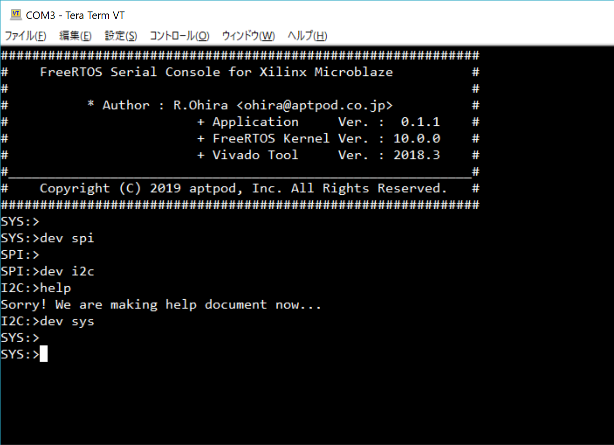
FPGAの制約ファイルで定義したI/Oピンに対して、PCからUSB-UART変換基板などを介してアクセスしましょう。(当たり前ですが)I/O電圧など間違えて基板を壊さないように…。TeratermでCOMポート接続してMicroBlazeを起動すると下記の画面が表示されます。

SYSプロンプトはMicroBlazeのメモリのR/W, Dumpなんかに使おうかと。
まとめ
Xilinxが提供する無償のソフトコアCPU、MicroBlazeでFreeRTOSを動作させてシリアル通信ターミナルを作りました。ベアメタルでEvent Drivenのステートマシンを作ってメンテに苦労してきた人間としては、**『FreeRTOS最高!圧倒的に楽!』**という感想です。設計中は割込み処理の周辺で結構ハマることも多かったのですが、ドキュメントも多いし海外のフォーラムでも情報がソコソコ活発にやりとりされていて助かりました。MITライセンスにしてくれたAmazonさんにも感謝です。MicroBlazeはVivado 2018.3の最新IPバージョンで64bit対応もされたようで、そちらの動作もチェックしたいところです。
次のステップとしては、FreeRTOSの各タスク効率化をもう少し頑張りたいところ。割込みで起こして処理が終わればBlocking状態にするとか。セマフォを使えばできるみたいなので、もうちょっとブラッシュアップしようと思います。
最後に人の募集です
aptpod Inc.ではInternet of Behaviorの世界の実現のためメンバーを募集しています。高粒度時系列データ(Fast Data)を処理するためのセンサ/基板・回路/FPGA/DSP/SoC/組込みソフト(ベアメタル、RTOS、Linux)など低レイヤをはじめ、インフラ・フロントエンド・UX・モバイル、データ解析・機械学習などのエンジニア職や、ソリューションアーキテクト・セールスといったビジネス開発の役割まで広く募集中です。
https://www.wantedly.com/companies/aptpod
デバイス設計からクラウド、UXまでの全てのレイヤを50人ぐらいの規模感で作り込めるチームってなかなか無いですし、アプリケーションも車載をはじめ、ロボット、ドローン、農業機械、産業機械などなど実に多彩です。ちょっと気になるなー、という方はぜひ一度オフィスにお越しください。Twitterで私にご一報頂けると色々とスムーズにお話できるかと思います。よろしくお願い致します。
