はじめに
前回の続きで,公式チュートリアルに沿ってPythonライブラリStimを使ってみる.
今回はより複雑な回路の作成・描画や,エラーの特定などを便利な機能を使って確認していく.
前回の記事
公式チュートリアル(英語)
反復符号の回路の作成
古典誤り訂正で用いられる反復符号を作成する.反復符号については,こちらのサイトを参考にした.
位相反転エラーのある量子回路では本来反復符号は使えないのだが,ひとまずこれを念頭に置きつつも回路を生成してみよう.
stim.Circuit.generatedは,引数にコードの種類を入れることでそのコードを追加してくれる.repetition_code:memoryで反復符号を指定できる.あとは,繰り返し回数や符合距離,エラーの種類をしてしてやればよい.
circuit = stim.Circuit.generated(
    "repetition_code:memory",
    rounds=25,
    distance=9,
    before_round_data_depolarization=0.04,
    before_measure_flip_probability=0.01)

print(repr(circuit))
circuit.diagram('timeline-svg')
roundsは繰り返し回数,distanceは符合距離である.before_round_data_depolarizationはランダムパウリエラー(depolarize)を各繰り返しの最初に発生させるというもので,確率を$p$としたとき
- $1-p$で$I$ゲート
- $p/3$で$X$ゲート
- $p/3$で$Y$ゲート
- $p/3$で$Z$ゲート
を発生させる.今回は$p = 0.04$である.
before_measure_flip_probabilityはその名の通り,測定結果が一定確率で反転するというものである.
実行結果
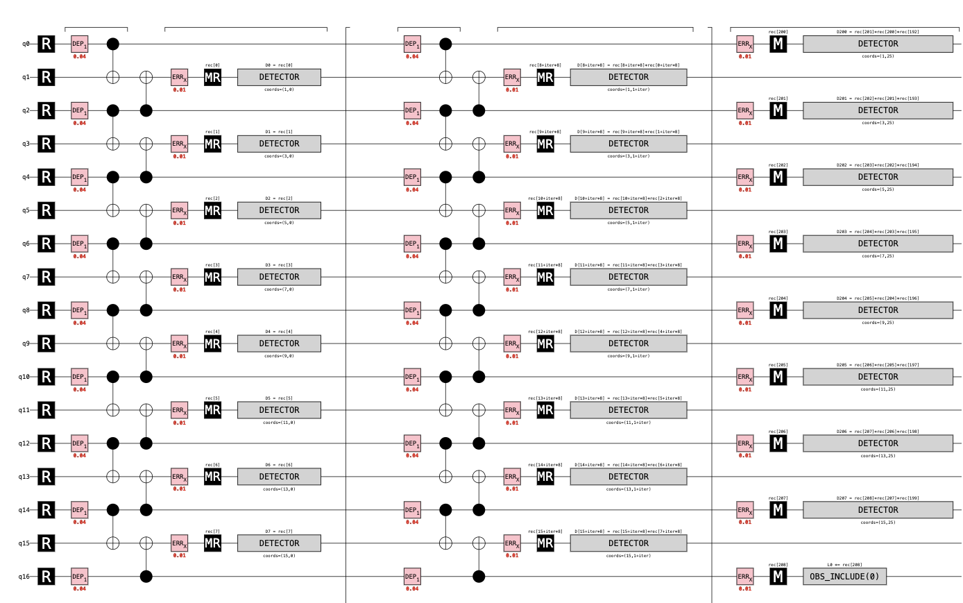
6行程度の短いコードでこんなに大きな回路が作れた.真ん中の部分は繰り返しになっていて,24個分の繰り返しが折りたたまれている.また,符合距離が9で量子ビット数が17になっていることにも注目だ.反復符号は古典誤り訂正符号であり,符号距離$d = \frac{n-1}2$でかかれ,それが成り立っていることがわかる.
これを表面符号でも試してみよう.
repetition_code:memoryの部分をsurface_code:rotated_memory_xに変更するだけだ.
実行結果
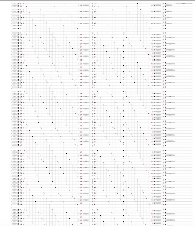
すごい実行結果がでてきた.なんと187量子ビットである.符合距離9が比較的大きいこともあるが,これで1論理ビットなのだから誤り訂正量子計算がいかに難しいかがわかると思う.
シンドローム測定とパリティ検査
さて,反復符号の例の方に戻ってどのように誤りが起きているかを測定してみよう.
先ほど出力した反復符号の回路をみると,縦に8個の測定が並んでいて,繰り返しによって何度も同じ量子ビットが測定されている.1回ショットを打った時の様子を調べてみよう.
sampler = circuit.compile_sampler()
one_sample = sampler.sample(shots=1)[0]
for k in range(0, len(one_sample), 8):
    timeslice = one_sample[k:k+8]
    print("".join("1" if e else "_" for e in timeslice))
実行結果
11______
11_11___
_1_11___
_1_11___
_1_11___
_11_1___
_11_1___
111__1__
111__1__
111_1___
111_1___
__1_1___
__111___
__1_1___
__1_1___
__1_1___
1_1_1___
1_1_1___
1_1_1___
1_1_1___
1_1_1___
1_1_1___
1_1_1___
1_1_1___
1_1_1___
1__11___
_
同じ行は同じ時刻,同じ列は同じ量子ビットになっている.Z測定をしたとき1が測定されたときには1,0のときには_が出力されるようになっている.みてすぐに気づくのは,1の列が縦に並んでいるということである.これは,パウリエラーが起きたときには測定されても状態自体が元に戻るわけではないため持続的にエラーとして検出されることによる.一方で,上下と比べ一個だけエラーをしているところもある.これは測定エラーによるもので,一時的に測定結果が反転することによる.
パリティチェックを使うことでより見通しよくエラーを判別することができる.
detector_sampler = circuit.compile_detector_sampler()
one_sample = detector_sampler.sample(shots=1)[0]
for k in range(0, len(one_sample), 8):
    timeslice = one_sample[k:k+8]
    print("".join("!" if e else "_" for e in timeslice))
実行結果
________
______!!
________
________
________
______!!
________
___!!___
______!_
______!_
________
________
________
________
____!!__
______!_
_____!_!
________
________
_______!
________
_!!_____
________
________
_____!__
_____!!!
!は必ず上下左右に隣接したもので1ペアになっているか,端にあるかになっているという性質を持つようにできている.このことを利用して,最小重みマッチングと呼ばれる組み合わせ問題を解いてエラーの場所を特定することができる.
エラーの訂正
デコーダに関してはあまりよく知らないのでざっと何をしているかだけを述べる.
上の例では,誤りをパリティで表示することにより見通しよくエラーを検出したが,検出器自体のエラーも存在する.このことを考慮したモデルを,検出器誤りモデル(error detecting model)という.
.detector_error_model()で回路の検出器誤りモデルを記述できる.
dem = circuit.detector_error_model()
print(repr(dem))
dem.diagram("matchgraph-svg")
実行結果
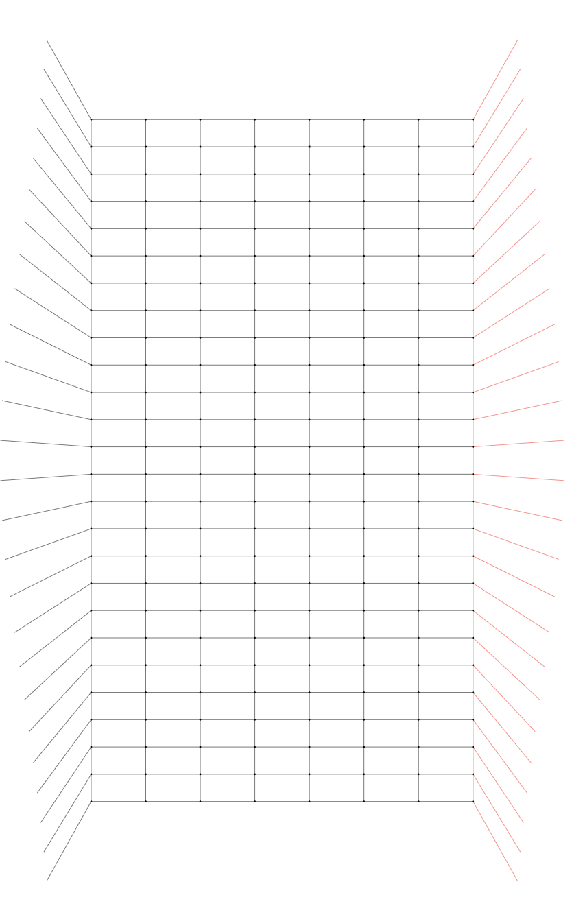
辺は検出器,頂点はエラーを表す.
実際にエラーを発生させた後,pymathingでデコーダを呼び出し,エラーを訂正してみよう.まずはライブラリのインストールをする.
%pip install pymatching
import pymatching
次に論理エラーのカウンターを定義する.
def count_logical_errors(circuit: stim.Circuit, num_shots: int) -> int:
    # 回路をサンプリングする.
    sampler = circuit.compile_detector_sampler()
    detection_events, observable_flips = sampler.sample(num_shots, separate_observables=True)

    # 回路からデコーダを構成する.
    detecter_error_model = circuit.detector_error_model(decompose_errors=True)
    matcher = pymatching.Matching.from_detector_error_model(detecter_error_model)

    # デコーダを実行する.
    predictions = matcher.decode_batch(detection_events)

    # 誤りをカウントする.
    num_errors = 0
    for shot in range(num_shots):
        actual_for_shot = observable_flips[shot]
        predicted_for_shot = predictions[shot]
        if not np.array_equal(actual_for_shot, predicted_for_shot):
            num_errors += 1
    return num_errors
それでは回路を設定して論理エラーを訂正できるか確認しよう.
circuit = stim.Circuit.generated("repetition_code:memory", rounds=100, distance=9, before_round_data_depolarization=0.03)
num_shots = 100_000
num_logical_errors = count_logical_errors(circuit, num_shots)
print("there were", num_logical_errors, "wrong predictions (logical errors) out of", num_shots, "shots")
実行結果
there were 8 wrong predictions (logical errors) out of 100000 shots
繰り返し数100,符合距離9の反復符号で,繰り返しごとに0.03の確率でランダムパウリエラーが起きるという回路となっている.また,繰り返しごとの測定で誤りを訂正するということを行なっている.一番最後の出力がエラーとなっているかを判定して間違っていたらwrong predictionである.100000 shotsのうち8 wrong errorsだから,完璧ではないもののいい感じに訂正できていることがわかる.本来訂正なしであれば,0.03の確率で発生するエラーが100回分抽選されて余裕でノイズに埋もれてしまうはずである.
before_round_data_depolarizationの値を変えればエラー率を変えることができる.結果は以下のような感じになった.
| エラー率 /% | 100000回中の論理エラー回数 |
| 3 | 8 |
| 6 | 136 |
| 9 | 834 |
| 12 | 3138 |
0.01の確率で測定にエラーが発生する状況を作ってみよう.before_measure_flip_probability=0.01を追加するだけだ.上と同様に各繰り返しに起きるパウリエラーの確率を変えて実行してみた.
| エラー率 /% | 100000回中の論理エラー回数 |
| 3 | 40 |
| 6 | 648 |
| 9 | 3433 |
| 12 | 9461 |
測定エラーが全く発生しないときより論理エラー率が大きくなったことがわかる.今度は,パウリエラー率を0.03に固定して測定エラー率を変えてみよう.
| 測定エラー率 /% | 100000回中の論理エラー回数 |
| 1 | 38 |
| 2 | 89 |
| 3 | 119 |
| 4 | 214 |
当然ではあるが,測定エラー率が大きくなると論理エラーが増えることがわかる.
最後に,エラー率と符合距離を変えたときの論理エラー率をグラフにしてみよう.エラーはランダムパウリエラーのみで測定エラーはなし.エラー率は0.1, 0.2, 0.3, 0.4, 0.5の5種類.符号距離は3, 5, 7の3種類.各条件ごとに10000 shotを打つ.
import matplotlib.pyplot as plt

num_shots = 10_000
for d in [3, 5, 7]:
    xs = []
    ys = []
    for noise in [0.1, 0.2, 0.3, 0.4, 0.5]:
        circuit = stim.Circuit.generated(
            "repetition_code:memory",
            rounds=d * 3,
            distance=d,
            before_round_data_depolarization=noise)
        num_errors_sampled = count_logical_errors(circuit, num_shots)
        xs.append(noise)
        ys.append(num_errors_sampled / num_shots)
    plt.plot(xs, ys, label="d=" + str(d))
plt.loglog()
plt.xlabel("phisical error rate")
plt.ylabel("logical error rate per shot")
plt.legend()
plt.show()
実行結果
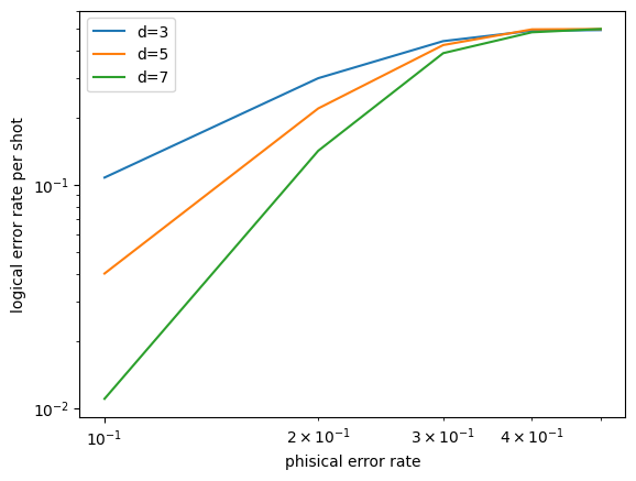
エラー率を下げた上で符合距離を大きくすると論理エラー率が下がるという結果が得られた.
おわりに
大きい回路を作ってみたり,エラーのある回路のシミュレーションをしたりした.訂正に関してはライブラリが全部やってくれたのでいつかそのあたりを詳しく掘り下げたい.
次回は表面符合の視覚化や閾値の推定を行う.