本記事の目的
こちらの素晴らしい記事でcartographerの使い方を学んだので、本記事ではcartographerとmove_baseを組み合わせて簡易的なnavigationを行います。
環境
本記事は以下の環境で実験しています.
| 項目 | バージョン |
|---|---|
| Ubuntu | 18.04 |
| ROS | Melodic |
| RPLidar | A1 M8 |
| Arduino | Mega2560 |
cartographerのインストール
以下のコマンドでcartographerをインストールします。
$ sudo apt install ros-melodic-cartographer-ros
cartographerの動作確認(地図生成)
とりあえずcartographerを動かしたい方は以下の記事を参考にして実行してみてください!
ここでは必要なコマンドのみ記載致します。
- リポジトリのcolne
$ cd ~/catkin_ws/src
$ git clone https://github.com/Andrew-rw/gbot_core.git
$ cd ..
$ catkin_make
- launch file実行
$ source ~/catkin_ws/devel/setup.bash
$ roslaunch gbot_core gbot.launch
- rvizでの可視化
$ source ~/catkin_ws/devel/setup.bash
$ roslaunch gbot_core visualization.launch
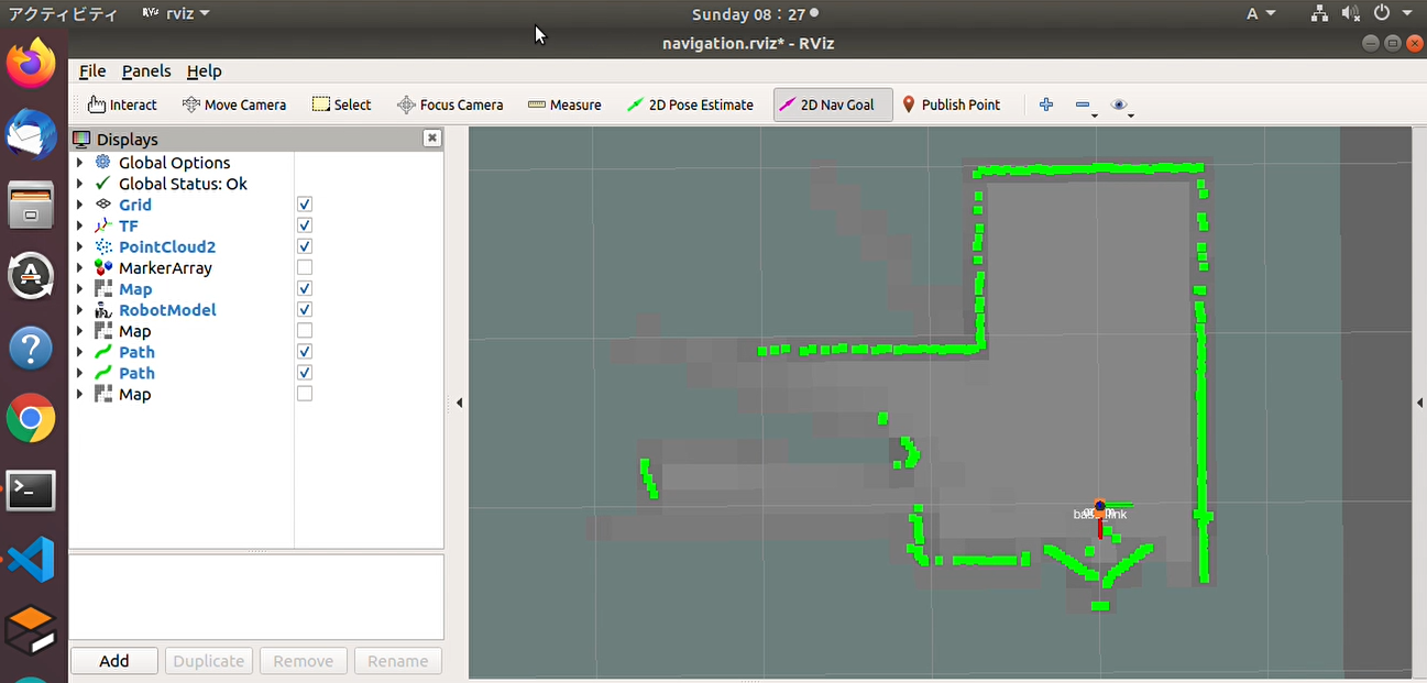
成功すると以下のように地図生成を行う事が出来ます!
cartographerでnavigationを行う
地図生成が行えたので次にnavigationを実行してみます。まずはROSでnavigationを行うのに必要なパッケージをインストールします。
$ sudo apt-get install ros-melodic-ddynamic-reconfigure
$ sudo apt-get install ros-melodic-tf2-sensor-msgs
$ sudo apt-get install ros-melodic-move-base
$ sudo apt-get install -y ros-melodic-gmapping ros-melodic-amcl ros-melodic-map-server
$ sudo apt-get install ros-melodic-dwa-local-planner
$ sudo apt-get install -y ros-melodic-robot-localization
次に以下のgithubをcloneしてください
$ git clone https://github.com/TUKUBA-CHALLENGE/cartgrapher_navigation.git
$ cd ~/catkin_ws
$ catkin_make
上記リポジトリはこちらのリポジトリをベースにnavigationにも対応できるようにしたものになります。ここでは主要なlaunchファイル(cartgrapher_navigation.launch)についてのみ説明します。
launchファイルでは基本的に以下の手順が実行されています。
- ロボットモデルを取り込む
- rplidar A1 M8のnodeを実行
- cartographer_nodeに対してluaファイルで事前設定したパラメータを渡す
- cartographer_occupancy_grid_nodeを実行。ここでresolutionの設定も行う
- move_baseに必要なyamlファイルを取り組む
- 可視化のためのrvizを立ち上げる
<launch>
    <!-- 1 : Load robot description and start state publisher-->
    <param name="robot_description" textfile="$(find cartgrapher_navigation)/urdf/robot_model.urdf" />
    <node name="robot_state_publisher" pkg="robot_state_publisher" type="robot_state_publisher" />

	<!-- 2 : Start RPLIDAR sensor node which provides LaserScan data  -->
    <node name="rplidarNode" pkg="rplidar_ros" type="rplidarNode" output="screen">
        <param name="serial_port" type="string" value="/dev/ttyUSB0"/>
        <!--<param name="serial_baudrate" type="int" value="115200"/>-->
        <param name="serial_baudrate"     type="int"    value="256000"/>
        <param name="frame_id" type="string" value="laser"/>
        <param name="inverted" type="bool" value="false"/>
        <param name="angle_compensate" type="bool" value="true"/>
    </node>

    <!-- 3 : outdoor -->
    <node name="cartographer_node" pkg="cartographer_ros" type="cartographer_node" args="
          -configuration_directory
              $(find cartgrapher_navigation)/configuration_files
          -configuration_basename outdoor_2d.lua" output="screen">
    </node>

	<!-- 4 : Additional node which converts Cartographer map into ROS occupancy grid map. Not used and can be skipped in this case -->
    <!--<node name="cartographer_occupancy_grid_node" pkg="cartographer_ros" type="cartographer_occupancy_grid_node" args="-resolution 0.05" />-->
    <node name="cartographer_occupancy_grid_node" pkg="cartographer_ros" type="cartographer_occupancy_grid_node" args="-resolution 0.15" />

    <!-- 5 : move base -->
    <node pkg="move_base" type="move_base" respawn="false" name="move_base" output="screen">
      <param name="base_local_planner" value="dwa_local_planner/DWAPlannerROS" />
      <rosparam file="$(find cartgrapher_navigation)/param/costmap_common_params.yaml" command="load" ns="global_costmap"/>
      <rosparam file="$(find cartgrapher_navigation)/param/costmap_common_params.yaml" command="load" ns="local_costmap"/>
      <rosparam file="$(find cartgrapher_navigation)/param/local_costmap_params.yaml" command="load"/>
      <rosparam file="$(find cartgrapher_navigation)/param/global_costmap_params.yaml" command="load"/>
      <!--<rosparam file="$(find cartgrapher_navigation)/param/base_local_planner_params.yaml" command="load"/>-->
      <rosparam file="$(find cartgrapher_navigation)/param/dwa_local_planner_params.yaml" command="load" />
      <rosparam file="$(find cartgrapher_navigation)/param/move_base_params.yaml" command="load"/>
    </node>

    <!-- 6 : Start RViz with custom view -->
    <node pkg="rviz" type="rviz" name="show_rviz" args="-d $(find cartgrapher_navigation)/rviz/navigation.rviz"/>
</launch>
上記navigationを実行してrviz上で2D_nav_goalを指定すれば指定速度、指令角速度がtopicとして吐き出されます。この速度と角速度をrosserialを使用してArduino側で受け取り、その値から左右に加えるべき角速度に変換後、PWM信号をモータに送ります。Arduino側のcodeは例えば以下のようなものを使用します。
# include <ros.h>
# include <ArduinoHardware.h>
# include <geometry_msgs/Twist.h>

/***********************************************************************
 * Macro
 **********************************************************************/
# define EN_L 12
# define IN1_L 7
# define IN2_L 8

# define EN_R 11
# define IN1_R 5
# define IN2_R 6

/***********************************************************************
 * Global variables
 **********************************************************************/
double w_r = 0.0;
double w_l = 0.0;

//wheel_rad is the wheel radius ,wheel_sep is
double wheel_rad = 0.03;
double wheel_sep = 0.32;

double speed_ang = 0.0;
double speed_lin = 0.0;

/***********************************************************************
 * Function
 **********************************************************************/
void messageCb( const geometry_msgs::Twist& msg){
  speed_ang = msg.angular.z;
  speed_lin = -msg.linear.x;
  w_r = (speed_lin/wheel_rad) + ((speed_ang*wheel_sep)/(2.0*wheel_rad));
  w_l = (speed_lin/wheel_rad) - ((speed_ang*wheel_sep)/(2.0*wheel_rad));
}

// ROS
ros::NodeHandle nh;
ros::Subscriber<geometry_msgs::Twist> sub("cmd_vel", &messageCb );

/***********************************************************************
 * prottype
 **********************************************************************/
void Motors_init();
void MotorL(int Pulse_Width1);
void MotorR(int Pulse_Width2);

void setup(){
  Motors_init();
  nh.initNode();
  nh.subscribe(sub);
}

void loop(){
  MotorL(w_l * 30);
  MotorR(w_r*  30);
  nh.spinOnce();
}

/***********************************************************************
 * Function
 **********************************************************************/
void Motors_init(){
    pinMode(EN_L, OUTPUT);
    pinMode(EN_R, OUTPUT);
    pinMode(IN1_L, OUTPUT);
    pinMode(IN2_L, OUTPUT);
    pinMode(IN1_R, OUTPUT);
    pinMode(IN2_R, OUTPUT);
    digitalWrite(EN_L, LOW);
    digitalWrite(EN_R, LOW);
    digitalWrite(IN1_L, LOW);
    digitalWrite(IN2_L, LOW);
    digitalWrite(IN1_R, LOW);
    digitalWrite(IN2_R, LOW);
}

void MotorL(int Pulse_Width1){
 if (Pulse_Width1 > 0){
     if (Pulse_Width1 > 240) {
        Pulse_Width1 = 240;
     }

     analogWrite(EN_L, Pulse_Width1);
     digitalWrite(IN1_L, LOW);
     digitalWrite(IN2_L, HIGH);
     /*digitalWrite(IN1_L, LOW);
     digitalWrite(IN2_L, HIGH);*/
 }

 if (Pulse_Width1 < 0){
     Pulse_Width1=abs(Pulse_Width1);
     if (Pulse_Width1 > 240) {
        Pulse_Width1 = 240;
     }

     analogWrite(EN_L, Pulse_Width1);
     digitalWrite(IN1_L, HIGH);
     digitalWrite(IN2_L, LOW);
     /*digitalWrite(IN1_L, LOW);
     digitalWrite(IN2_L, HIGH);*/
 }

 if (Pulse_Width1 == 0){
     analogWrite(EN_L, Pulse_Width1);
     digitalWrite(IN1_L, LOW);
     digitalWrite(IN2_L, LOW);
 }
}

void MotorR(int Pulse_Width2){
 if (Pulse_Width2 > 0){
     if (Pulse_Width2 > 240) {
        Pulse_Width2 = 240;
     }

     analogWrite(EN_R, Pulse_Width2);
     digitalWrite(IN1_R, LOW);
     digitalWrite(IN2_R, HIGH);
     /*digitalWrite(IN1_R, HIGH);
     digitalWrite(IN2_R, LOW);*/
 }

 if (Pulse_Width2 < 0){
     Pulse_Width2=abs(Pulse_Width2);
     if (Pulse_Width2 > 240) {
        Pulse_Width2 = 240;
     }

     analogWrite(EN_R, Pulse_Width2);
     digitalWrite(IN1_R, HIGH);
     digitalWrite(IN2_R, LOW);
     /*digitalWrite(IN1_R, LOW);
     digitalWrite(IN2_R, HIGH);*/
 }

 if (Pulse_Width2 == 0){
     analogWrite(EN_R, Pulse_Width2);
     digitalWrite(IN1_R, LOW);
     digitalWrite(IN2_R, LOW);
 }
}
上記のcodeについては以下の記事でも紹介しているので、こちらも参考にしてください。
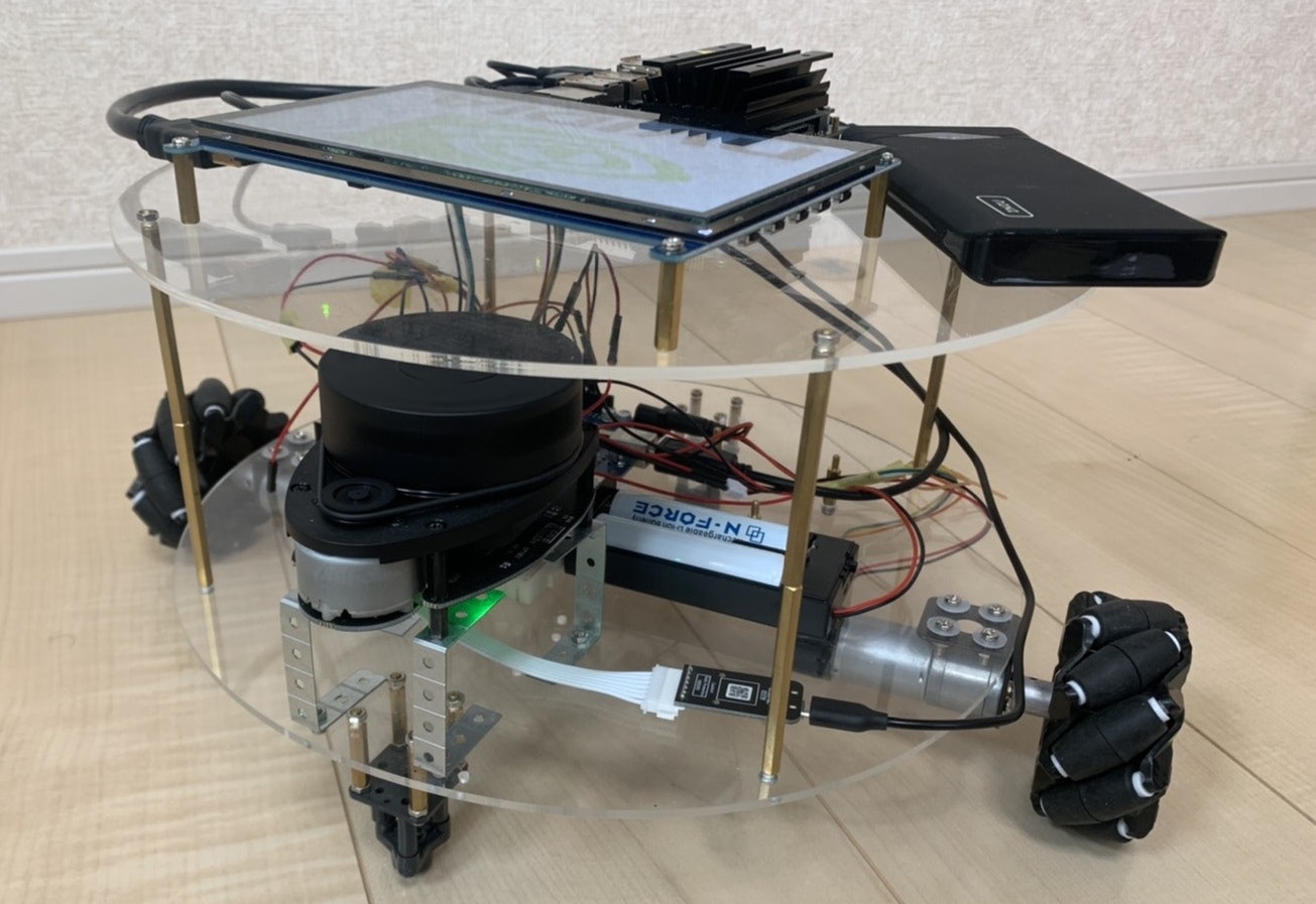
それでは以下のようなロボットを用意しましょう(笑)このような簡易的なロボットの作成手順についても上記の記事で解説しているので、参考にしながら自作してみると楽しいと思います!
ロボットの準備が出来たら以下のコマンドを実行してnavigationを実行してみましょう!
$ sudo chmod 666 /dev/ttyUSB0
$ sudo chmod 666 /dev/ttyACM0
$ rosrun rosserial_python serial_node.py /dev/ttyACM0 _baud:=115200
$ roslaunch cartgrapher_navigation cartgrapher_navigation.launch
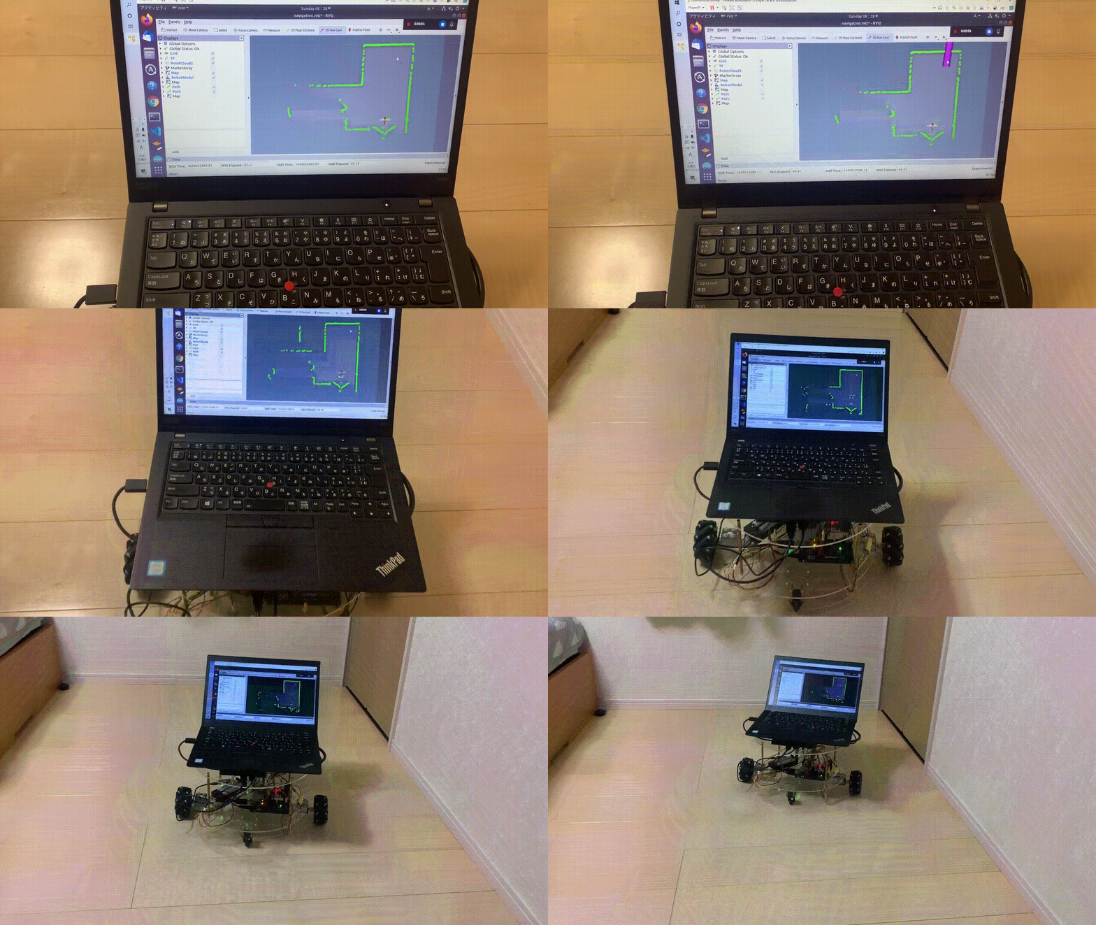
上記のlaunchファイルを実行するとrvizが立ち上がります。rvizで2D_Nav_Goalを適当に指定すると、その方向に向かってnavigationしていく様子が見れます。以下二つのgifはrviz, 実環境共に対応しているものになります。ゴール判定が指定した場所の手前になっていますが、こちらはローカルプランナーのゴール判定範囲を0.3mと設定しているためです。
まとめ
- cartographerとmove_baseを組み合わせて簡易的なnavigationを行いました
参考文献


