はじめに
ニキシー管時計づくりにチャレンジしてみました。
前回、NTP と RTC による時刻の管理を行いました。
今回は、それと前々回のニキシー管のダイナミック点灯のプログラムと組み合わせ、ニキシー管時計プログラムを完成させます。
他の記事はこちらから
- part 0:事前学習&準備編
- part 1:昇圧チョッパ編
- part 2:ニキシー管点灯編
- part 3:NTPとRTCで時間管理編
- part 4:プログラム完成編
- part 5:comming soon...(?)
回路図
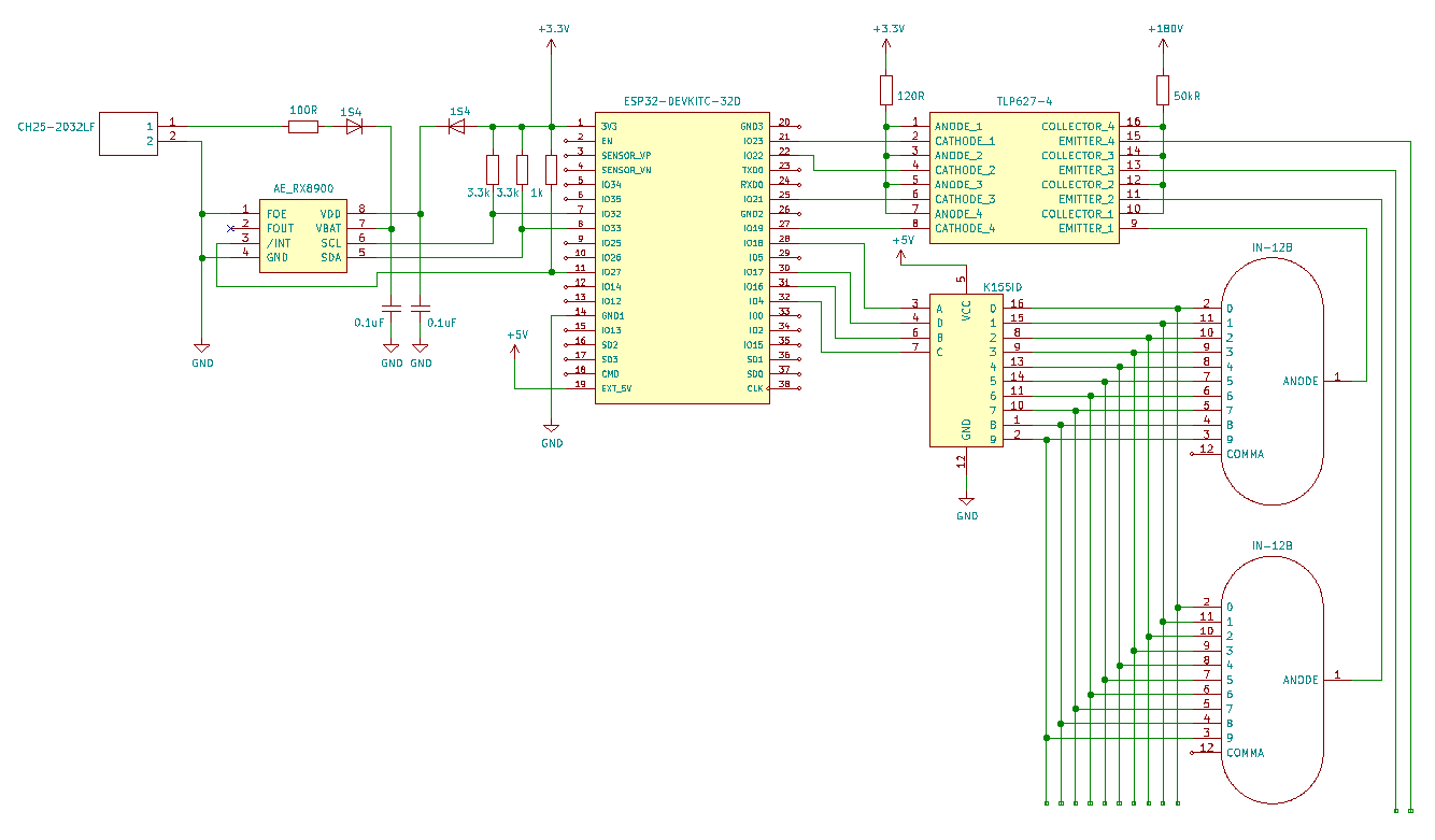
回路図はこんな感じです。
2025/06/02 追記
VDDとVBATに0.1μFのバイパスコンデンサを追加。
VBATに電流制限抵抗を追加。
SCL , SDA , /INT にプルアップ抵抗を追加。
値は全てアプリケーションマニュアルを参考にしました。

前回と前々回の回路をそのまま合体させただけです。例のごとくニキシー管は 2 つまでしか描いていません。
ニキシー管時計プログラム
以下が作成したプログラムです。
前回までで作成した NTP.h 、RTC.h および RTC.cpp もそのまま使用します(これらのファイルの説明は前回の記事)。
( GitHub のリンク)
#pragma once
#include <Arduino.h>
#include <unordered_map>
#include "Nixie.h"

/* 時計の桁を表す列挙型 */
enum class Digit : uint8_t {
  HR_L, HR_R, MIN_L, MIN_R
};

/* Digitの各要素と、任意の型のデータを紐づける辞書型のエイリアステンプレート */
template<typename T>
using dgt_t_umap = std::unordered_map<Digit, T>;

/* 4つのニキシー管を制御するクラス */
class NixieClock {
  private:
    constexpr static uint32_t  ON_TIME_MICRO = 4000; // オン時間
    constexpr static uint32_t OFF_TIME_MICRO =  380; // オフ時間
    uint32_t switched_time; // 点灯消灯の切り替え時刻
    bool     on_flag;       // 点灯フラグ
    dgt_t_umap<Nixie>                 dgt_nix_umap; // 4桁分のニキシー管を扱うunordered_map
    dgt_t_umap<Nixie>::const_iterator dgt_nix_iter; // 現在扱っている桁

  public:
    NixieClock(const dgt_t_umap<NixiePinInfo> _dgt_pinf_umap); // コンストラクタ
    void setup();                                              // 初期設定
    void setTime(const struct tm *tm);                         // すべての管に時刻をセット
    void lightup();                                            // すべての管を点灯
    void shuffle(const uint8_t n);                             // シャッフル点灯
};
#include <random>
#include "NixieClock.h"

/* コンストラクタ */
NixieClock::NixieClock(const dgt_t_umap<NixiePinInfo> _dgt_pinf_umap) :
  dgt_nix_umap{
    {Digit::HR_L,  Nixie(_dgt_pinf_umap.at(Digit::HR_L))},
    {Digit::HR_R,  Nixie(_dgt_pinf_umap.at(Digit::HR_R))},
    {Digit::MIN_L, Nixie(_dgt_pinf_umap.at(Digit::MIN_L))},
    {Digit::MIN_R, Nixie(_dgt_pinf_umap.at(Digit::MIN_R))},
  }
{}

/* 初期設定 */
void NixieClock::setup() {
  dgt_nix_iter = dgt_nix_umap.begin(); // 最初の桁
  dgt_nix_iter->second.lightOn();      // 点灯
  switched_time = micros();            // 点灯時刻を記録
  on_flag = true;                      // フラグを立てる
}

/* すべての管に時刻をセット */
void NixieClock::setTime(const struct tm *tm) {
  dgt_nix_umap.at(Digit::HR_L ).setNum(tm->tm_hour/10);
  dgt_nix_umap.at(Digit::HR_R ).setNum(tm->tm_hour%10);
  dgt_nix_umap.at(Digit::MIN_L).setNum(tm->tm_min/10);
  dgt_nix_umap.at(Digit::MIN_R).setNum(tm->tm_min%10);
}

/* すべての管を点灯 */
void NixieClock::lightup() {
  if (on_flag) { // オン時
    if (micros() - switched_time > ON_TIME_MICRO) { // 点灯時間終了
      dgt_nix_iter->second.lightOff(); // 消灯
      on_flag = false;                 // フラグを降ろす
      switched_time = micros();        // 切り替え時刻更新
    }
  }
  else { // オフ時
    if (micros() - switched_time > OFF_TIME_MICRO) { // 消灯時間終了
      if(++dgt_nix_iter == dgt_nix_umap.end()){
        dgt_nix_iter = dgt_nix_umap.begin();
      }
      dgt_nix_iter->second.lightOn(); // 点灯
      on_flag = true;                 // フラグを立てる
      switched_time = micros();       // 切り替え時刻更新
    }
  }
}

/* シャッフル点灯 */
void NixieClock::shuffle(const uint8_t n = 1) {
  const uint8_t  NUM_OF_NUMBERS     = 10;
  const uint32_t SHUFFLE_SPAN_MILLI = 30;
  uint32_t previous;
  static dgt_t_umap<std::array<uint8_t, NUM_OF_NUMBERS>> dgt_ary_umap = {
    {Digit::HR_L,  {0, 1, 2, 3, 4, 5, 6, 7, 8, 9}},
    {Digit::HR_R,  {0, 1, 2, 3, 4, 5, 6, 7, 8, 9}},
    {Digit::MIN_L, {0, 1, 2, 3, 4, 5, 6, 7, 8, 9}},
    {Digit::MIN_R, {0, 1, 2, 3, 4, 5, 6, 7, 8, 9}}
  }; // ランダム表示させる数列のunordered_map

  std::random_device rd; // 乱数生成エンジン
  std::mt19937 mt(rd()); // 疑似乱数生成エンジン
  for(uint8_t _n = 0; _n < n; ++_n) {
    for(auto& [dgt, ary] : dgt_ary_umap){
      std::shuffle(ary.begin(), ary.end(), mt); // 数列をシャッフル
    }
    for(uint8_t i = 0; i < NUM_OF_NUMBERS; ++i) {
      for(auto& [dgt, ary] : dgt_ary_umap){
        dgt_nix_umap.at(dgt).setNum(ary[i]);
      }
      previous = millis();
      while(millis() - previous < SHUFFLE_SPAN_MILLI) {
        lightup();
      }
    }
  }
}
#include "NTP.h"
#include "RTC.h"
#include "NixieClock.h"

const char*   SSID = "YOUR_SSID";     // SSID
const char*   PASS = "YOUR_PASSWORD"; // パスワード
const uint8_t PIN_SCL         = 32;   // I2C通信用のピン
const uint8_t PIN_SDA         = 33;   //
const uint8_t PIN_N_INT       = 27;   // 割り込みを検知するピン
const uint8_t PIN_ANODE_HR_L  = 23;   // 4つのニキシー管のアノードのピン
const uint8_t PIN_ANODE_HR_R  = 22;   //
const uint8_t PIN_ANODE_MIM_L = 21;   //
const uint8_t PIN_ANODE_MIM_R = 19;   //
const uint8_t PIN_CATHODE_A   = 18;   // カソードの制御ピン
const uint8_t PIN_CATHODE_B   = 16;   //
const uint8_t PIN_CATHODE_C   = 4;    //
const uint8_t PIN_CATHODE_D   = 17;   //

NTP ntp(SSID, PASS); // NTPクラスのインスタンスを生成

const RTCPinInfo rtcPinInfo {
  PIN_SCL,
  PIN_SDA,
  PIN_N_INT
};
RTC rtc(rtcPinInfo); // RTCクラスのインスタンスを生成

const dgt_t_umap<NixiePinInfo> dgt_pinf_umap = {
  {Digit::HR_L,  {PIN_ANODE_HR_L,  PIN_CATHODE_A, PIN_CATHODE_B, PIN_CATHODE_C, PIN_CATHODE_D}}, // 時の左側
  {Digit::HR_R,  {PIN_ANODE_HR_R,  PIN_CATHODE_A, PIN_CATHODE_B, PIN_CATHODE_C, PIN_CATHODE_D}}, // 時の右側
  {Digit::MIN_L, {PIN_ANODE_MIM_L, PIN_CATHODE_A, PIN_CATHODE_B, PIN_CATHODE_C, PIN_CATHODE_D}}, // 分の左側
  {Digit::MIN_R, {PIN_ANODE_MIM_R, PIN_CATHODE_A, PIN_CATHODE_B, PIN_CATHODE_C, PIN_CATHODE_D}}, // 分の左側
};
NixieClock nixie_clock(dgt_pinf_umap); // NixieClockクラスのインスタンスを生成

bool tick_flag = false;                  // 時間更新割り込み発生フラグ
void setupTickFlag() {tick_flag = true;} // 時間更新割り込み時に実行する関数
struct tm tm;                            // 時刻保存用の構造体


void setup() {
  ntp.setup();
  rtc.setup();
  rtc.setISR(setupTickFlag);
  if(ntp.getIsConfigured()) { // Wi-Fi接続成功時
    ntp.getTime(&tm);
    rtc.setDateTime(&tm); // RTCに時刻を保存
    ntp.disconnect();
  }
  else { // Wi-Fi接続失敗時
    // 何もしない
  }

  nixie_clock.setup();
  nixie_clock.shuffle(3);
  rtc.getDateTime(&tm);
  nixie_clock.setTime(&tm);
}

void loop() {
  nixie_clock.lightup();

  if(tick_flag) { // 割り込み発生(「分」が更新)
    rtc.getDateTime(&tm);
    if(tm.tm_min == 0) { // 「時」が変わったらシャッフル
      nixie_clock.shuffle(1);
    }
    nixie_clock.setTime(&tm);
    tick_flag = false; // フラグを降ろす
  }
}
NixieClock クラスは、前々回の NixieController クラスを少し書き換えたものです。
具体的には 2 つの関数が異なります。
まず setNums() 関数が setTime() 関数に代わっています。
この関数は構造体 tm を受け取り、その時と分で 4 つのニキシー管の表示する数字を書き換えます。
/* すべての管に時刻をセット */
void NixieClock::setTime(const struct tm *tm) {
  dgt_nix_umap.at(Digit::HR_L ).setNum(tm->tm_hour/10);
  dgt_nix_umap.at(Digit::HR_R ).setNum(tm->tm_hour%10);
  dgt_nix_umap.at(Digit::MIN_L).setNum(tm->tm_min/10);
  dgt_nix_umap.at(Digit::MIN_R).setNum(tm->tm_min%10);
}
もう 1 つは shuffle() 関数です。完全に趣味のために追加しました。
/* シャッフル点灯 */
void NixieClock::shuffle(const uint8_t n = 1) {
  const uint8_t  NUM_OF_NUMBERS     = 10;
  const uint32_t SHUFFLE_SPAN_MILLI = 30;
  uint32_t previous;
  static dgt_t_umap<std::array<uint8_t, NUM_OF_NUMBERS>> dgt_ary_umap = {
    {Digit::HR_L,  {0, 1, 2, 3, 4, 5, 6, 7, 8, 9}},
    {Digit::HR_R,  {0, 1, 2, 3, 4, 5, 6, 7, 8, 9}},
    {Digit::MIN_L, {0, 1, 2, 3, 4, 5, 6, 7, 8, 9}},
    {Digit::MIN_R, {0, 1, 2, 3, 4, 5, 6, 7, 8, 9}}
  }; // ランダム表示させる数列のunordered_map

  std::random_device rd; // 乱数生成エンジン
  std::mt19937 mt(rd()); // 疑似乱数生成エンジン
  for(uint8_t _n = 0; _n < n; ++_n) {
    for(auto& [dgt, ary] : dgt_ary_umap){
      std::shuffle(ary.begin(), ary.end(), mt); // 数列をシャッフル
    }
    for(uint8_t i = 0; i < NUM_OF_NUMBERS; ++i) {
      for(auto& [dgt, ary] : dgt_ary_umap){
        dgt_nix_umap.at(dgt).setNum(ary[i]);
      }
      previous = millis();
      while(millis() - previous < SHUFFLE_SPAN_MILLI) {
        lightup();
      }
    }
  }
}
各桁にそれぞれ 0 ~ 9 が入れられた配列をあてがい、配列内をランダムに入れ替えます。
30 ミリ秒の間隔でそれらを順に表示し、これを引数で指定された回数繰り返します。
nixie_clock では、これまでの集大成として NTP クラス、RTC クラス、NixieClock クラスそれぞれのインスタンスを生成し、適宜機能を呼び出しています。
プログラムの機能は以下のような感じです。
- 電源投入直後
- ネットワークに接続
- 成功:NTP により ESP32 の時刻合わせを行う
- 失敗:何もしない
- RTC に時刻を保存
- ネットワーク接続成功時:現在時刻に更新
- ネットワーク接続失敗時:すでに保存された時刻のまま
- ニキシー管を 3 回シャッフル点灯
- ニキシー管の表示時刻を更新
- ネットワークに接続
- メインループ
- ニキシー管を点灯
- 割り込み(分の更新)を監視
- 割り込み発生時
- ニキシー管の表示時刻を更新
- 更新後の分が「 0 」(時も変更)の場合、シャッフル点灯
動作確認
実行してみます。
スマホの画面に表示されているのは、例のごとく NICT の日本標準時です。
電源投入直後
しっかり時刻の取得ができています。
なぜシャッフルするのか? かっこいいから。
分の更新
分の更新もばっちりです。
遅延も見られず、NTP によって精度よく時刻を取得できていることが分かります。
時の更新
こちらのシャッフルも問題ないですね。
なぜシャッフルするのか? かっk
おわりに
これは...「「 時計 」」...!
次回から、地獄の本体設計編が開幕します。
次回:comming soon...(?)
