環境
・PIC16F1827
・MPLAB X IDE v5.25
・Arduino nano互換機(テスト用I2C Master)
参考にさせて頂いたサイト
Configuration Bit の設定
私がよく使う設定を流用。
main.c
// CONFIG1
# pragma config FOSC = INTOSC    // Oscillator Selection (INTOSC oscillator: I/O function on CLKIN pin)
# pragma config WDTE = ON        // Watchdog Timer Enable (WDT enabled)
# pragma config PWRTE = ON       // Power-up Timer Enable (PWRT enabled)
# pragma config MCLRE = ON       // MCLR Pin Function Select (MCLR/VPP pin function is MCLR)
# pragma config CP = OFF         // Flash Program Memory Code Protection (Program memory code protection is disabled)
# pragma config CPD = OFF        // Data Memory Code Protection (Data memory code protection is disabled)
# pragma config BOREN = ON       // Brown-out Reset Enable (Brown-out Reset enabled)
# pragma config CLKOUTEN = OFF   // Clock Out Enable (CLKOUT function is disabled. I/O or oscillator function on the CLKOUT pin)
# pragma config IESO = OFF       // Internal/External Switchover (Internal/External Switchover mode is disabled)
# pragma config FCMEN = OFF      // Fail-Safe Clock Monitor Enable (Fail-Safe Clock Monitor is disabled)

// CONFIG2
# pragma config WRT = OFF        // Flash Memory Self-Write Protection (Write protection off)
# pragma config PLLEN = ON       // PLL Enable (4x PLL enabled)
# pragma config STVREN = ON      // Stack Overflow/Underflow Reset Enable (Stack Overflow or Underflow will cause a Reset)
# pragma config BORV = HI        // Brown-out Reset Voltage Selection (Brown-out Reset Voltage (Vbor), high trip point selected.)
# pragma config LVP = ON         // Low-Voltage Programming Enable (Low-voltage programming enabled)
PICの初期化
内部クロックGPIOの初期化。
main.c
/void main(void)
    OSCCON = 0xF2;  /* 内部クロック:8MHz */
    ANSELA = 0x00;
    ANSELB = 0x00;
    TRISA = 0x00;
    TRISB = 0x00;
    PORTA = 0x00;
    PORTB = 0x00;

    ...
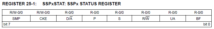
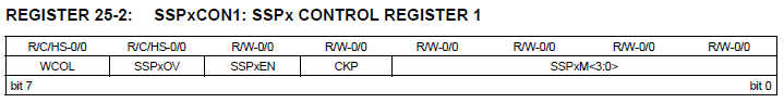
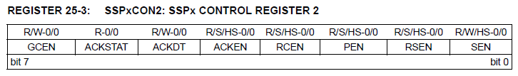
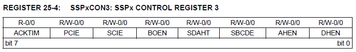
I2C初期設定
今回はスレーブモード、7bitアドレスモードで初期化。
main.c
    SSP1CON2 = 0x01;            /* クロックストレッチ有効 */
    SSP1CON3 = 0x00;            /* データホールド有効 */
    SSP1ADD = I2C_ADDR<<1;      /* スレーブアドレスの設定 */
    SSP1STAT = 0x00;            /* ハイスピードモード/ SM Bus無効 */
    SSP1CON1 = 0b00110110;      /* I2Cスレーブモード/7bitアドレスモード */