I2C通信において、SDAラインへのデータ出力(データ変更)および、[sample, capture]のタイミングについての調査。
リンク
https://en.wikipedia.org/wiki/I%C2%B2C
Timing diagramの画像があり、その説明が以下。
2.SDA sets the 1st data bit level while keeping SCL low (during blue bar time) .
3.The data is sampled (received) when SCL rises (green) for the first bit (B1).
...
In order to avoid false marker detection, SDA is changed on the SCL falling edge and is sampled and captured on the rising edge of SCL.
https://e2e.ti.com/support/microcontrollers/msp430/f/166/t/183280 > I2C specs are that the data lien is allowed to change while SCL is low. Not a tthe beginning or the end, not after or before or at an edge, but any time while SCL is low.
http://www.nxp.com/documents/user_manual/UM10204.pdf
例
例として、以下の場合。
- ACK読取り
- 3つのDAT読取り
- ACK書込み
タイミングチャートとしては以下のような感じだろうか。
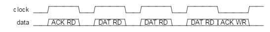
clock  __~~~~__~~~~__~~~~__~~~~____~~
data   __=ACK RD===__=DAT RD===__=DAT RD===__=DAT RD===X=ACK WR==__