概要
BluemixのRaspberryPi登録レシピに登場するデバイス用のsampleプログラムは、どんなにセンサーがたくさん付いていようが固定の4項目のデータのみをBluemixに送信する作りになっている。
Raspberry Pi 2にセンサーを付け加えて固定4項目以外のデータをBluemixで取得するには、sampleプログラムのソースコードを修正してビルドすれば良い。その方法を整理する。
整理している内に長くなってきたので、(1)Sampleプログラムの仕組みの整理と(2)どこをどのように変更すればよいのかを分けることにした。
(1) 仕組みの理解
(2) センサーを付けてデータを拾う 温度センサーデジタル編
(3) センサーを付けてデータを拾う 温度センサーアナログ編(これ)
(4) センサーを付けてデータを拾う 温度センサーデジタル編(リベンジ)
(5) センサーを付けてデータを拾う 温度・湿度・気圧まとめて採取編
番外編 『ムック「日経Linux ラズパイマガジン 2015年春号 」電子工作入門キット パーツセット』に入っていたもの
前提
RaspberryPi2がBluemixのIoTFサービスに「レシピ」を使って接続済みであること。
回路(ネタ)
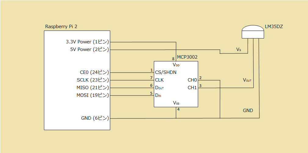
ムック「日経Linux ラズパイマガジン 2015年春号 」第3部 はじめての電子工作ステップ50の内、「No.34 A/D変換機を実際に活用 アナログ温度センサーで温度を測定してみよう」に記載されている回路でやってみる。
掲載されていた図(Excelで作図)
ムックには「MISO (22ピン)」と記載されていたが「MISO (21ピン)」の誤植ではないかと思うので修正した。
回路(設計)
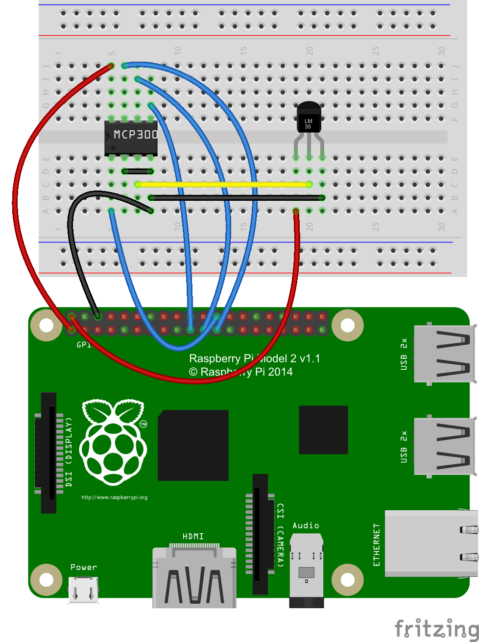
元ネタの図の通りにFritzingで作ってみた。
MCP3002のパーツはここからから入手して、Fritzingにインポートした。
http://fritzing.org/media/fritzing-repo/projects/r/rpi-radio/fritzing/RPi_radio.fzz
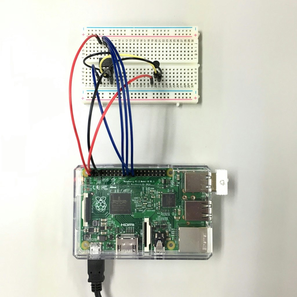
回路(実装)
Raspberry Pi 2上でSPIの有効化
作業はRaspberry Pi 2にログインして行う。
実行時ユーザは次の通り
$ : pi
# : root
WiringPiの導入
# cd /var/tmp
# git clone git://git.drogon.net/wiringPi
# cd wiringPi
# ./build
導入確認のためにバージョンを確認してみる。
# gpio -v
バージョンが表示されること。
SPI有効化
Raspberry Pi 2はraspi-configから設定する。
# raspi-config
「8 Advanced Options」を選択して、「Select」を押下

再起動後にSPI用のモジュールが読み込まれていることを確認する。
$ lsmod | grep spi
「spi_bcm2708」が表示されること。
Raspberry Pi 2上で温度を読んでみる
ムック読者限定サイトに用意されたプログラム「adc_lm35dz.c」をコンパイル・実行してみる。
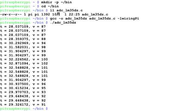
画面に温度を出力する。5秒間隔で20回。
センサーを指でつまむと温度が上がり、離すと下がる。
$ mkdir -p ~/bin
$ cd ~/bin
$ ll adc_lm35dz.c
$ gcc -o adc_lm35dz adc_lm35dz.c -lwiringPi
$ ./adc_lm35dz
画面出力例)
t = 28.037109, v = 87
v : 読み取った値
t : 温度 (100 * 3.3 * v / 1024で計算した結果)
プログラムの改修内容
BluemixのRaspberryPi登録レシピに登場するデバイス用のsampleプログラムを次の通り修正する。
修正前のソースコードはこちらで参照可能
| 修正するファイル | 新規で追加するファイル |
|---|---|
| iotmain.c iot.h jsonator.c Makefile |
lm35dz.c |
追加・修正内容は以下の通り。
修正内容1
//lm35dz.c
float getLm35dzTemp();
修正内容2
		JsonMessage json_message = { DEVICE_NAME, getCPUTemp(), sineVal(
				MIN_VALUE, MAX_VALUE, 16, count), GetCPULoad() };
		JsonMessage json_message = { DEVICE_NAME, getCPUTemp(), sineVal(
				MIN_VALUE, MAX_VALUE, 16, count), GetCPULoad(), getLm35dzTemp() };
修正内容3
  struct json {
	  char myname[100];
	  float cputemp;
	  float sine;
	  float cpuload;
  };
  struct json {
	  char myname[100];
	  float cputemp;
	  float sine;
	  float cpuload;
	  float lm35dztemp;
  };
修正内容4
	strcat(jsonReturned, ",");

	strcat(jsonReturned, "\"lm35dztemp\":");
	sprintf(buffer, "%.2f", passedrpi.lm35dztemp);
	strcat(jsonReturned, buffer);
修正内容5
iot: iotmain.c cpustat.c mac.c mqttPublisher.c jsonator.c iot.h jsonReader.c
	export LIBRARY_PATH=$(COMPILELIBDIR):$(LIBRARY_PATH)
	$(CC) iotmain.c cpustat.c mac.c mqttPublisher.c jsonator.c cJSON.c jsonReader.c -o $@ -l$(LIBNAME) -lpthread -lssl -lm -L $(COMPILELIBDIR) -I .
iot: iotmain.c cpustat.c mac.c mqttPublisher.c jsonator.c iot.h jsonReader.c lm35dz.c
	export LIBRARY_PATH=$(COMPILELIBDIR):$(LIBRARY_PATH)
	$(CC) iotmain.c cpustat.c mac.c mqttPublisher.c jsonator.c cJSON.c jsonReader.c lm35dz.c -o $@ -l$(LIBNAME) -lpthread -lssl -lwiringPi -lm -L $(COMPILELIBDIR) -I .
追加内容1 (ムック読者限定サイトに用意されたプログラム「adc_lm35dz.c」をベースに作成)
# include <stdio.h>
# include <stdlib.h>
# include <string.h>
# include <wiringPi.h>

const int PI_CE  = 0; // CE0を使う場合は 0、CE1を使う場合は 1を指定
const int ADC_CH = 1; // ADコンバータのCH0を使う場合は 0、CH1を使う場合は 1を指定
const int CLOCK_SPEED = 3200000; // 500,000 から 32,000,000 の間で指定

unsigned int readMCP3002(int pi_channel, int adc_channel);
float getLm35dzTemp();

unsigned int readMCP3002(int pi_channel, int adc_channel) {
  unsigned int v = 0;
  unsigned char data[2] = {};
  data[0] |= 0x60; // ここでは固定
  data[0] |= adc_channel==0 ? 0x00 : 0x10; // ADコンバータのCH0、CH1のどちらを使うかで変わる
  wiringPiSPIDataRW(pi_channel, data, 2);  // pi_channelにつなげたADコンバータからSPIでデータ読み取り
  v = ((data[0] & 0x03) << 8) + data[1];   // 1バイト目の下位2ビットと2バイト目にデータ値が入っているので取り出す
  return v;
}

float getLm35dzTemp() {
  unsigned int v; // MCP3002から読み取った値
  float t; // 温度
  int i;   // カウンタ
  if (wiringPiSPISetup(PI_CE, CLOCK_SPEED) < 0) { // SPI初期化
    return EXIT_FAILURE;
  }
  v = readMCP3002(PI_CE, ADC_CH);
  t = 100.0 * 3.3 * (float)v / 1024.0;
  return t;
}
プログラムの改修手順
作業はRaspberryPi2にログインして行う。
実行時ユーザは次の通り
$ : pi
# : root
-
設定ファイルの退避
# cd /etc/iotsample-raspberrypi/
# cp -p device.cfg device.cfg.`date +%Y%m%d`_1
※これで、アンインストール(dpkg -P)してもフォルダとバックアップファイルが残るので安心。 -
必要パッケージのインストール
# apt-get install dpkg-dev build-essential devscripts
# apt-get install libssl-dev -
ソースコード一式を入手
$ cd ~
$ git clone https://github.com/ibm-messaging/iot-raspberrypi.git -
ソースコード修正・追加
$ cd ~/iot-raspberrypi/samples/c/
$ vi iotmain.c
$ vi iot.h
$ vi jsonator.c
$ vi Makefile
$ vi lm35dz.c -
ビルド
$ debuild -b
署名のエラーは無視する。
iotサービスの再インストール
-
アンインストール(古いのを)
# dpkg -P iot -
インストール
# cd /home/pi/iot-raspberrypi/samples/
# dpkg -i ./iot_1.0-1_armhf.deb -
サービスの確認
# service iot status
※起動している(okが表示される)こと。 -
設定ファイル作成
# cd /etc/iotsample-raspberrypi/
# cp -p device.cfg.`date +%Y%m%d`_1 device.cfg
※6.でいったん削除されてしまうので、1.で退避したファイルで復元 -
サービスの再起動
# service iot restart
※起動している(okが表示される)こと。 -
起動モードの確認
# service iot getdeviceid
※registerd mode で起動している(registerd modeが表示される)こと。
Bluemix IoT Foundationサービスで確認
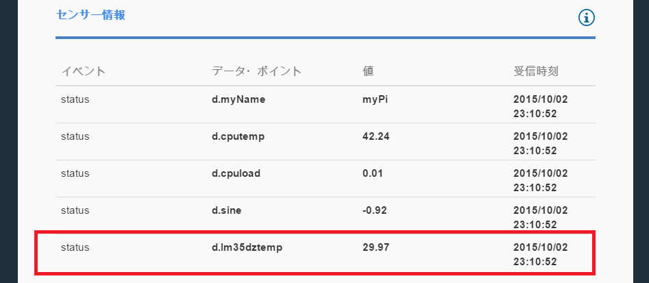
IoT Foundationのダッシュボードで、センサー情報欄にて確認する。
センサーの温度データを受信できた!
所感
「/sys/class/gpio配下を参照する」というのはなんだったのか。。。
デジタルの温度センサーや他のセンサーはそれで行けるのか??
続き
(4) センサーを付けてデータを拾う 温度センサーデジタル編(リベンジ)
環境
Raspberry Pi 2 Model B
Raspbian
Bluemix IoT Foundation
参考
Fritzingダウンロード
http://fritzing.org/download/
Fritzing用のMCP3002のパーツ
http://fritzing.org/media/fritzing-repo/projects/r/rpi-radio/fritzing/RPi_radio.fzz
BluemixのRaspberryPi登録レシピ
https://developer.ibm.com/recipes/tutorials/raspberry-pi-4/
BluemixのRaspberryPi登録レシピに登場するデバイス用のsampleプログラム
(Linux用のdaemonになっている)
https://github.com/ibm-messaging/iot-raspberrypi/blob/master/samples/c/
