HOLTEK社製のHT16K33というLED Controller DriverをopenFramewokrsからシリアルで点灯させてみようと思います。
ドライバ単体をそのまま動作させるのは大変なので、Adafruitから出ているHT16K33 Breakoutを使うのがおすすめです。
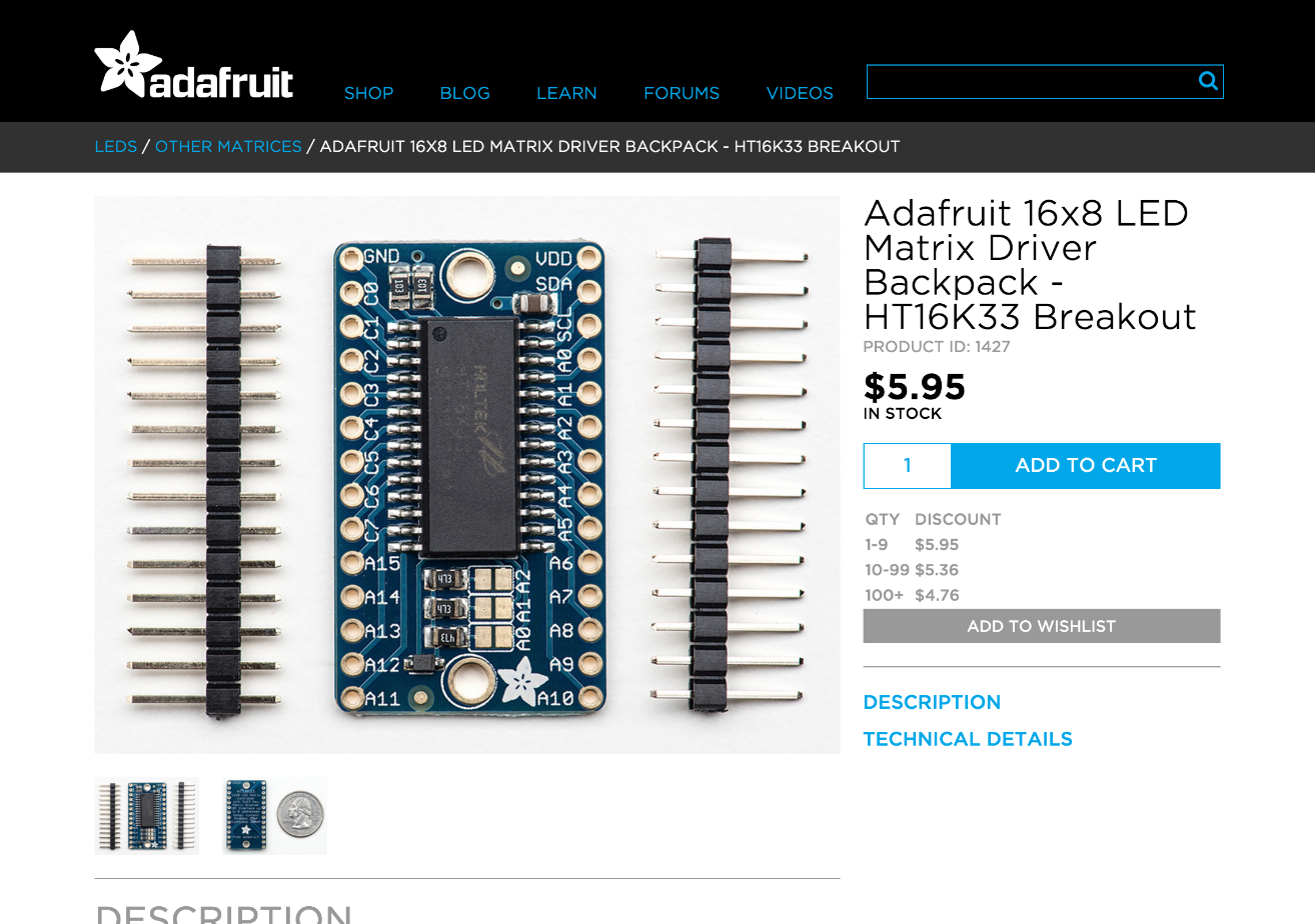
これはArduinoのI2CでLEDのマトリクスを制御出来るというものなのですが、制御できる数は最大16x8で、7セグなどのLEDも動かせます。
同時に3つほど繋げて動作させられるので、3つ使えば16x24のLEDパネルとして使用出来ます。
また、Arduinoから点灯を制御するには、Adafruit製の"Adafruit_LEDBackpack.h"と"Adafruit_GFX.h"を読みこめば比較的簡単に動かすことが出来ます。
https://github.com/adafruit/Adafruit-LED-Backpack-Library
https://github.com/adafruit/Adafruit-GFX-Library
また、Breakoutと秋月とかのLEDマトリクスを接続することも可能ですが、ここらへんのドライバと基板とLEDがセットになったもののほうが手軽に使えます。
https://www.adafruit.com/products/1853
https://www.adafruit.com/products/2052
組み立て方や接続方法などはこちらをご覧ください。
https://learn.adafruit.com/downloads/pdf/adafruit-led-backpack.pdf
ちなみに普通のLEDマトリクスを接続して使う場合はこちらのブログを参考に接続してみてください。
HT16K33を2つ使ってLEDドットマトリックスを制御してみた
http://nuneno.cocolog-nifty.com/blog/2015/01/ht16k33led-1282.html
本題にはいります。
先に記したとおり、Arduinoからドライバを制御するのはライブラリを使えば簡単に出来ます。
ただ、openFrameworksから制御するのが結構厄介で(今思うと、素直にI2Cをfirmata経由で動かすのが良い)、僕が試したのは下記のようにoFからシリアル経由でArduinoに信号を送り、点灯させるという方法です。
openFrameoworks → シリアル → Arduino UNO → HT16K33 → LEDマトリクス
で、Arduino側のソースはこんな感じです。詳しくはコメントをご覧ください。
#include <Wire.h>
#include "Adafruit_LEDBackpack.h"
#include "Adafruit_GFX.h"

// 6x18の場合のLEDの個数
#define LED_SIZE 128

// HT16K33の接続台数
int enables[3] = {true, true, false};
// それぞれのID
int drivers[3] = {0x70, 0x71, 0x72};
// それぞれの明るさ
int brightnesses[3] = {0, 0, 0};

int mode = 0;
String numberString = "";
int numbers[LED_SIZE*3] = {};
int counter = -1;

// Adafruit_LEDBackpackを配列にする
Adafruit_8x16matrix matrixes[3] = {
  Adafruit_8x16matrix(),
  Adafruit_8x16matrix(),
  Adafruit_8x16matrix()
};

void setup() {
  // シリアル通信を開始
  Serial.begin(115200);

  // それぞれのドライバーのinitialize
  if(enables[0]){
    matrixes[0].begin(drivers[0]);
    matrixes[0].setBrightness(brightnesses[0]);
  }

  if(enables[1]){
    matrixes[1].begin(drivers[1]);
    matrixes[1].setBrightness(brightnesses[1]);
  }

  if(enables[2]){
    matrixes[2].begin(drivers[2]);
    matrixes[2].setBrightness(brightnesses[2]);
  }
}

void loop() {
  // シリアルポートにデータがあるか
  if (Serial.available() > 0) {
    // シリアルポートにあるデータの先頭1byteを取得
    char input = Serial.read();
    int il = sizeof(input);

    // 取得したデータの分だけループ
    for(int i = 0; i < il; i++){
      char c = input;
      // charをintに変換
      int ctoi = input - '0';

      // シリアルデータの接頭文字がHだったら
      if(c == 'H'){
        mode = 11;
        numbers[counter] += numberString.toInt() + 1;
        numberString = "";
        counter++;
      }
      // シリアルデータの接頭文字がスラッシュだったら
      else if(c == '/'){
        mode = 19;
        numbers[counter] += numberString.toInt() + 1;
        numberString = "";
      }
      // シリアルデータが数値だったら(LEDの点灯場所)
      else if(int(ctoi) >= 0 && int(ctoi) <= 9){
        // 接頭文字がHの時
        if(mode == 11){
          // 連続した数値を保存("2","5","6"のようにバラバラで取得したものを"256"とする)
          numberString += String(c);
        }
        // 接頭文字がスラッシュの時(シリアルデータの取得完了時)
        else if(mode == 19){
          // 変数をinitialize
          memset( numbers, 0, sizeof(numbers) );
          counter = -1;
          mode = 0;
        }
      }
    }

    // シリアルデータの取得完了時の処理(LEDの点灯処理)
    if(mode == 19){
      int nl = sizeof(numbers) / sizeof(numbers[0]);

      if(enables[0]) matrixes[0].clear();
      if(enables[1]) matrixes[1].clear();
      if(enables[2]) matrixes[2].clear();

      int numberCount = 0;
      for(int i = 0; i < nl; i++){
        int n = numbers[i];
        if(n > 0){
          n -= 1;
          int y = 0;
          int x = 0;

          // 連番で来た数値をx,y座標に戻す
          if(n < LED_SIZE){
            y = floor(n / 8);
            x = n - (floor(n / 8) * 8);
            if(enables[0]) matrixes[0].drawPixel(x, y, LED_ON);
          }
          else if(n < LED_SIZE * 2){
            n -= LED_SIZE;
            y = floor(n / 8);
            x = n - (floor(n / 8) * 8);
            if(enables[1]) matrixes[1].drawPixel(x, y, LED_ON);
          }
          else if(n < LED_SIZE * 3){
            n -= LED_SIZE * 2;
            y = floor(n / 8);
            x = n - (floor(n / 8) * 8);
            if(enables[2]) matrixes[2].drawPixel(x, y, LED_ON);
          }
          numberCount++;
        }
      }

      if(numberCount > 0){
      }

      // LEDを点灯
      if(enables[0]) matrixes[0].writeDisplay();
      if(enables[1]) matrixes[1].writeDisplay();
      if(enables[2]) matrixes[2].writeDisplay();
    }

  }
}
このソースをArduinoに書き込んだ後、HT16K33のBreakoutなどに接続します。
そしてopenFrameworks側では、シリアルに接続した後、下記のようなルールでシリアルポートにデータを書き込みます。
"H" +(左上からのLEDの連番)... 繰り返し... "\0"
void ofApp::updateSerial(){
  string writerSerial += "H1H200H37H184/0";
  unsigned char* writeByte = (unsigned char*) writerSerial.c_str();
  int result = serial.writeBytes(writeByte, writerSerial.length() + 1);
}
これがシリアルでの送信の基本で、これをもうすこし使える感じにしたものはこちらです。
https://github.com/hisahayashi/ofxHT16K33
動作サンプル
※ openFrameworks側の黒い丸とLEDの点灯が連動しています