Here is my hardware and software design of a dual function decoder for DCC, model train digital command control. The assumed usage is to control LEDs.
ABSTRACT
- Microprocessor: Atmel 8-bit AVR ATtiny10: 1024 bytes flash. 32 bytes SRAM. No EEPROM.
- Partial conformance with NMRA's DCC standards. Functionality of F0, FL in NMRA, follows Digitrax's behavior.
- Records the time of DCC signal edges on the PB1 pin using the Input Capture Unit of 16-bit Timer/Counter0.
- Toggles the level of the PB0 and PB3 pins to control the LED intensities by PWM. Output Compare Unit of 16-bit Timer/Counter0 is used for this functionality. The processor's own PWM capability is not used because one of the two PWM available pins is overlapped with the Input Capture Pin.
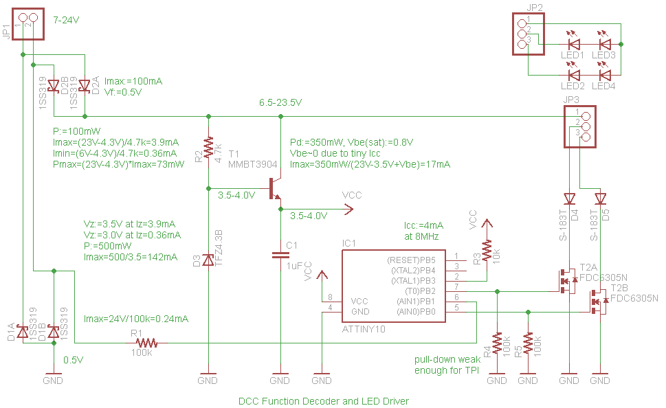
CIRCUIT
CODE
Build environment:
- Atmel Studio 6 (Version: 6.1.2730 - Service Pack 2)
- Atmel AVR 8-bit GNU Toolchain - 3.4.3.1072 (gcc-4.8.1)
Build result:
- Program Memory Usage : 1022 bytes 99.8 % Full
- Data Memory Usage : 12 bytes 37.5 % Full
/*
    Copyright (C) 2014 Takuya Nishida

    Permission is hereby granted, free of charge, to any person obtaining a copy
    of this software and associated documentation files (the "Software"), to deal
    in the Software without restriction, including without limitation the rights
    to use, copy, modify, merge, publish, distribute, sublicense, and/or sell
    copies of the Software, and to permit persons to whom the Software is
    furnished to do so, subject to the following conditions:

    The above copyright notice and this permission notice shall be included in
    all copies or substantial portions of the Software.

    THE SOFTWARE IS PROVIDED "AS IS", WITHOUT WARRANTY OF ANY KIND, EXPRESS OR
    IMPLIED, INCLUDING BUT NOT LIMITED TO THE WARRANTIES OF MERCHANTABILITY,
    FITNESS FOR A PARTICULAR PURPOSE AND NONINFRINGEMENT. IN NO EVENT SHALL THE
    AUTHORS OR COPYRIGHT HOLDERS BE LIABLE FOR ANY CLAIM, DAMAGES OR OTHER
    LIABILITY, WHETHER IN AN ACTION OF CONTRACT, TORT OR OTHERWISE, ARISING FROM,
    OUT OF OR IN CONNECTION WITH THE SOFTWARE OR THE USE OR OTHER DEALINGS IN
    THE SOFTWARE.
*/

#define F_CPU 8000000UL

#include <avr/io.h>
#include <avr/interrupt.h>
#include <avr/sleep.h>

// Configuration Values

#define DECODER_ADDRESS 0003
#define FUNCTION_A_0_4_1 0b00001
#define FUNCTION_A_12_5 0b00000000
#define FUNCTION_B_0_4_1 0b00100
#define FUNCTION_B_12_5 0b00000000
#define INTENSITY_A 0x8000
#define INTENSITY_B 0x8000
#define SWITCHING_RATE_A 0x0100
#define SWITCHING_RATE_B 0x0800

// Constants

#define PORTB_BIT_A _BV(0)
#define PORTB_BIT_B _BV(2)
#define FLAGS_BIT_0_ACCEPTED _BV(0)
#define FLAGS_BIT_1_ACCEPTED _BV(1)
#define FLAGS_DATA_BYTES_START_OR_END _BV(2)
#define FLAGS_FORWARD _BV(3)
#define MAX_PACKET_BYTES 4
#define INVALID_BIT_INDEX (8 * MAX_PACKET_BYTES)
#define INPUT_CAPTURE_PRESCALE 2

// Do not initialize variables with values except for zero
// in order to eliminate the setup code for the data memory.

static unsigned short lastEdgeTime;
static unsigned char flags;
static unsigned char timerOverflown;
static unsigned char continuous1;
static unsigned char bitIndex;
static unsigned char packet[MAX_PACKET_BYTES];
static unsigned char functions0_4_1;
static unsigned char functions12_5;

// Maximum stack usage is 13 bytes. Check .lss to count PUSHes.

int main(void)
{
    // System clock division factor = 1
    CCP = 0xD8;
    CLKPSR = 0x00;
    // Analog comparator disabled
    ACSR = _BV(ACD);
    // Shut down ADC
    PRR = _BV(PRADC);
    // In the case of power loss, the level of RESET remains HIGH because of
    // the capacitor. Meanwhile, Vcc becomes lower to the level that
    // the processor becomes unstable.
    // VLM causes reset interrupt if Vcc level becomes lower than VLM1L, 1.4V.
    VLMCSR = _BV(VLMIE) | _BV(VLM0);
    // Input capture noise canceler activated. Timer not prescaled
    TCCR0B = _BV(ICNC0) | _BV(CS00);
    // Interrupts enabled
    TIMSK0 = _BV(ICIE0) | _BV(TOIE0) | _BV(OCIE0A) | _BV(OCIE0B);
    // Data direction
    DDRB = PORTB_BIT_A | PORTB_BIT_B;
    // In the idle mode, CLKio is still active to drive the timer
    set_sleep_mode(SLEEP_MODE_IDLE);
    // Initialize variables
    bitIndex = INVALID_BIT_INDEX;
    // Start the loop
    sei();
    sleep_enable();
    for (;;) {
        sleep_cpu();
    }
    return 0;
}

ISR(TIM0_CAPT_vect) {
    unsigned char f = flags; // Copy to a local variable to reduce the data memory access
    // Scale by 2 to accept the longest legitimate duration for bit 0
    unsigned short edgeTime = ICR0 >> 1;
    if (timerOverflown & 0x01) {
        edgeTime |= 0x8000;
    }
    unsigned short duration = edgeTime - lastEdgeTime;
    lastEdgeTime = edgeTime;
    if (duration >= (unsigned short)(52L * F_CPU / 1000000L / INPUT_CAPTURE_PRESCALE) &&
        duration <= (unsigned short)(64L * F_CPU / 1000000L / INPUT_CAPTURE_PRESCALE)) {
        // Edge for a bit 1 detected
        f &= ~FLAGS_BIT_0_ACCEPTED;
        f ^= FLAGS_BIT_1_ACCEPTED;
        // Check if it is the second edge
        if (!(f & FLAGS_BIT_1_ACCEPTED)) {
            if (f & FLAGS_DATA_BYTES_START_OR_END) {
                // Date Byte End Bit detected
                f &= ~FLAGS_DATA_BYTES_START_OR_END;
                // Ignore the Error Detection Data Byte to save the code size
                // Extract the address and instruction
                union {
                    unsigned short s;
                    unsigned char ch[2];
                } address;
                unsigned char instruction;
                unsigned char p0 = packet[0], p1 = packet[1], p2 = packet[2];
                if (/*p0 != 0xFF && */(p0 & 0xC0) == 0xC0) { // omit checking broadcast to save the code size
                    address.ch[1] = p0 & 0x3F; // MSB
                    address.ch[0] = p1; // LSB
                    instruction = p2;
                } else {
                    address.s = (unsigned short)p0;
                    instruction = p1;
                }
                // Update variables according to the instruction
                if (address.s == DECODER_ADDRESS) {
                    switch (instruction & 0xE0) {
                    case 0x80:
                        functions0_4_1 = instruction & 0x1F;
                        break;
                    case 0xA0:
                        if (instruction & 0x10) {
                            functions12_5 = (functions12_5 & 0xF0) | (instruction & 0x0F);
                        } else {
                            functions12_5 = (functions12_5 & 0x0F) | (instruction << 4);
                        }
                        break;
                    case 0x40:
                        f &= ~FLAGS_FORWARD;
                        break;
                    case 0x60:
                        f |= FLAGS_FORWARD;
                        break;
                    }
                }
                bitIndex = INVALID_BIT_INDEX;
            } else if (bitIndex != INVALID_BIT_INDEX) {
                // Received a bit of the packet
                packet[bitIndex / 8] |= (1 << (7 - (bitIndex % 8)));
                ++bitIndex;
                if (bitIndex % 8 == 0) {
                    f |= FLAGS_DATA_BYTES_START_OR_END;
                }
            }
            // Wait for the preamble
            if (continuous1 < 0x80) { // must be 0x80 to generate SBRC Rd, 7
                ++continuous1;
            }
        }
    } else if (duration >= (unsigned short)(90L * F_CPU / 1000000L / INPUT_CAPTURE_PRESCALE) &&
        duration <= (unsigned short)(10000L * F_CPU / 1000000L / INPUT_CAPTURE_PRESCALE)) {
        // Edge for a bit 0 detected
        f &= ~FLAGS_BIT_1_ACCEPTED;
        f ^= FLAGS_BIT_0_ACCEPTED;
        // Check if it is the second edge
        if (!(f & FLAGS_BIT_0_ACCEPTED)) {
            if (f & FLAGS_DATA_BYTES_START_OR_END) {
                // Date Byte Start Bit detected
                f &= ~FLAGS_DATA_BYTES_START_OR_END;
            } else if (bitIndex != INVALID_BIT_INDEX) {
                // Received a bit of the packet
                packet[bitIndex / 8] &= ~(1 << (7 - (bitIndex % 8)));
                ++bitIndex;
                if (bitIndex % 8 == 0) {
                    f |= FLAGS_DATA_BYTES_START_OR_END;
                }
            }
            // Check if it is the end of preamble
            if (continuous1 > 12) {
                bitIndex = 0;
                f &= ~FLAGS_DATA_BYTES_START_OR_END;
            }
            continuous1 = 0;
        }
    } else {
        // Clear the states in case of invalid duration
        f &= ~(FLAGS_BIT_0_ACCEPTED | FLAGS_BIT_1_ACCEPTED);
        bitIndex = INVALID_BIT_INDEX;
        continuous1 = 0;
    }
    flags = f;
    // Next time, we want an opposite edge.
    TCCR0B ^= _BV(ICES0);
}

ISR(TIM0_OVF_vect) {
    // Count the pseudo MSByte of the timer.
    // MSBit is saturated after 0x80 * 0x10000 Timer0 clocks, 1.04 sec.
    timerOverflown = (timerOverflown + 1) | (timerOverflown & 0x80);
    // Adjust each pulse width according to the function status
    if ((functions0_4_1 & (!(flags & FLAGS_FORWARD) ? 0xEF : 0xFF) & FUNCTION_A_0_4_1) ||
        (functions12_5 & FUNCTION_A_12_5)) {
        if (INTENSITY_A - OCR0A < SWITCHING_RATE_A || !(timerOverflown & 0x80)) {
            // In case of power loss, intensity is immediately restored.
            OCR0A = INTENSITY_A;
        } else {
            OCR0A += SWITCHING_RATE_A;
        }
    } else {
        if (OCR0A < SWITCHING_RATE_A) {
            OCR0A = 0;
        } else {
            OCR0A -= SWITCHING_RATE_A;
        }
    }
    if ((functions0_4_1 & ((flags & FLAGS_FORWARD) ? 0xEF : 0xFF) & FUNCTION_B_0_4_1) ||
        (functions12_5 & FUNCTION_B_12_5)) {
        if (INTENSITY_B - OCR0B < SWITCHING_RATE_B || !(timerOverflown & 0x80)) {
            // In case of power loss, intensity is immediately restored.
            OCR0B = INTENSITY_B;
        } else {
            OCR0B += SWITCHING_RATE_B;
        }
    } else {
        if (OCR0B < SWITCHING_RATE_B) {
            OCR0B = 0;
        } else {
            OCR0B -= SWITCHING_RATE_B;
        }
    }
    // Do not set HIGH when the pulse width is zero.
    if (OCR0A > 0) {
        PORTB |= PORTB_BIT_A;
    }
    if (OCR0B > 0) {
        PORTB |= PORTB_BIT_B;
    }
}

ISR(TIM0_COMPA_vect) {
    // If OCR0 is close to the max value,
    // the timer could have been overflowed at this moment
    // because the priority of this interrupt is lower than the others.
    // So, turn off the output only if the timer is not overflowed yet.
    if (OCR0A <= TCNT0) {
        PORTB &= ~PORTB_BIT_A;
    }
}

ISR(TIM0_COMPB_vect) {
    // If OCR0 is close to the max value,
    // the timer could have been overflowed at this moment
    // because the priority of this interrupt is lower than the others.
    // So, turn off the output only if the timer is not overflowed yet.
    if (OCR0B <= TCNT0) {
        PORTB &= ~PORTB_BIT_B;
    }
}
NOTE: I found a bug in the code above. In rare condition, it should fail to calculate the right value of the pulse width, and it leads to missing a packet. It happens because timerOverflown and ICR0 are not in sync. When the timer overflows at the same time a signal edge is detected, TIM0_CAPT_vect is called before timerOverflown is updated in TIM0_OVF_vect.
AFTERTHOUGHTS
I do not think this design is feasible for a mobile function decoder on a train. Lack of EEPROM critically limits its applications. Though there are some workarounds as follows, I would rather turn to ATtiny25, ATtiny45 or ATtiny85 instead of complicated tweaks.
Pros
Tiny board dimensions thanks to an ATtiny10's SOT-23 package.
Cons
Not to mention a lack of features of reading/writing configuration variables, it cannot even retain the status of its functions when it loses power due to poor electrical contact between rails and wheels.
If sending packets from the command station repeated for all the trains, it would not be a problem. But actually it seems the command station sends packets only for the train that it has a throttle of. Therefore, it is fatal and unrecoverable that the decoder loses its status in momentary power loss.
Workarounds for cons
The capacitor helps a little to keep supplying the power to the processor during power loss. But from my experiment, a capacitor as large as 100uF only serves the power for around half a second.
Or, it may be possible to let the command station to keep sending packets for all the trains.
How about a backup battery? Hmm, I think this is where to stop.