普段はMac OS XでUrJTAGを使っているのだが、ByteBlasterMVをFreeBSDで試した流れで、UrJTAGにFreeBSD 11Rから提供されているlibgpioを使うドライバを書いてみた。
Linux用のgpio.cをベースにjtagの4本をlibgpioの関数に置き換えただけです。Linuxでは一本毎にopenしてfdを持っているようですが、libgpioではgpiocをopenしてそのfdで関数を呼んでいます。余談ですが、このgpio.cがFreeBSDでもコンパイルされてしまっているようなので、コンパイルは通るのですが、意味がないのでconfigure.acのチェックを見直した方が良いと思います。
コードを書くよりもautoconfの設定を作るのにずいぶん苦労した。
とりあえずgpioがあるMIPSルーター用にZRouterのportsに放り込んでビルドしてみた。ZRouterのportsはFreeBSD本体のportsと流れでビルドするのだが、Makefileはいろいろいじらなければならない。
試しにRT3050のJTAGポートからadm5120のJTAGポートに接続してRT3050でUrJTAGを動かしてみた。adm5120のTRST(1)は100Ωでプルアップしています。
RT3050はFDTでのコンフィグレーションでカーネルをビルドしてあり、JTAGポートはgpioで使うようにdtsに設定してあります。参考:sys/mips/mediatekのpinコントロール
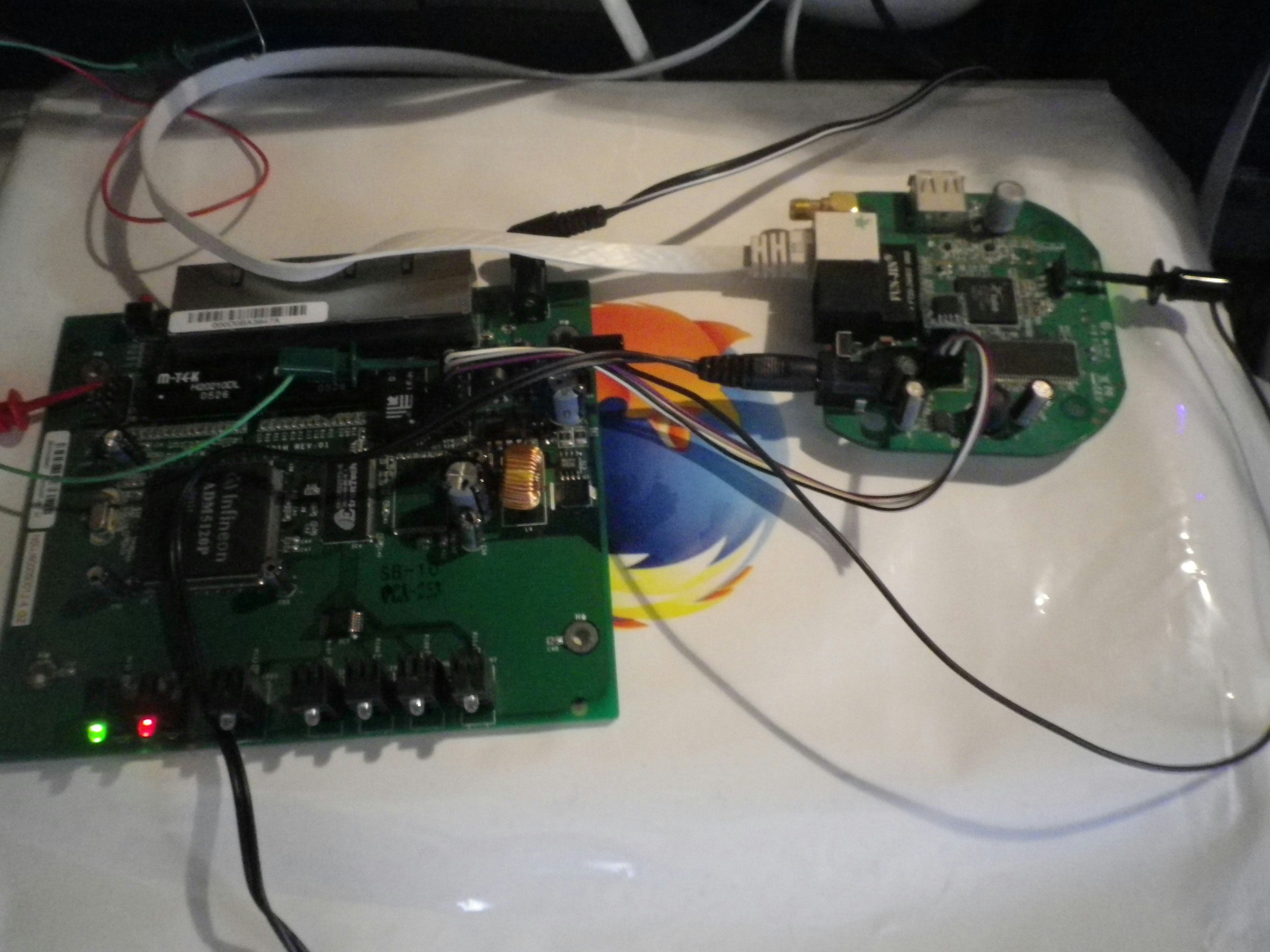
4本の2mmから2.54mmの変換ケーブルをQIコネクタで作ってみました。2mmのQIコネクタは難しくてあまり旨く作れなかったんで、導通チェックしてとりあえず使えているようです。
# ./jtag

UrJTAG 0.10 #
Copyright (C) 2002, 2003 ETC s.r.o.
Copyright (C) 2007, 2008, 2009 Kolja Waschk and the respective authors

UrJTAG is free software, covered by the GNU General Public License, and you are
welcome to change it and/or distribute copies of it under certain conditions.
There is absolutely no warranty for UrJTAG.

warning: UrJTAG may damage your hardware!
Type "quit" to exit, "help" for help.

warning: system error: Read-only file system cannot mkdir(/root/.jtag)
jtag> cable bsdgpio tdi=18 tdo=17 tms=19 tck=20
Initializing GPIO JTAG Chain
jtag> detect
IR length: 5
Chain length: 1
Device Id: 00000000000000000000000000000001 (0x00000001)
  Unknown manufacturer! (00000000000) (/usr/local/share/urjtag/MANUFACTURERS)
jtag> include admtek/adm5120/adm5120
ImpCode=01000001010000000100000000000000 41404000
EJTAG version: 2.6
EJTAG Implementation flags: R4k DINTsup ASID_8 NoDMA MIPS32
Processor entered Debug Mode.
jtag> print
 No. Manufacturer              Part                 Stepping Instruction
  Register
--------------------------------------------------------------------------------
-----------------------------------
   0                                                         EJTAG_DATA
  EJDATA

Active bus:
*0: EJTAG compatible bus driver via PrAcc (JTAG part No. 0)
        start: 0x00000000, length: 0x20000000, data width: 8 bit
        start: 0x20000000, length: 0x20000000, data width: 16 bit
        start: 0x40000000, length: 0x20000000, data width: 32 bit
jtag> peek 0x52000000
URJ_BUS_READ(0x52000000) = 0x34085120 (872960288)
jtag>
Switch Control Register(Base Address 1200 0000H)のCode Register(Offset Address 00H)を32ビットで見てみました。下位が5120となっていてデータシートと一致して正しくアクセスできているのが分かります。
このターゲットのadm5120pはgpioが4本あります。
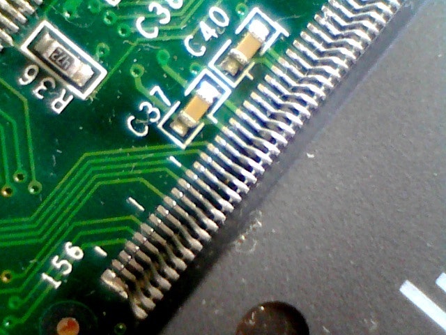
148ピンから151ピンまでがGPIOです。148ピン(GPIO3)と151ピン(GPIO0)がどこかに接続されているようです。
GPIOレジスタに書き込んでみます。
jtag> poke 0x520000b8 0x08080000
148ピン(GPIO3)が赤いLEDに接続されているので、上記の操作でLEDが消灯します。
ちなみにGPIO0はFlashのWPに接続さているようです。
ADM5120でbootが残っていれば初期化しているのでdetectflashが使えますが、Flashが空になった場合などは初期化が必要なようです。
この情報は海外の人の書き込みが元のようなのですが、海外の人は違うターゲットで試したと思われ、同じようにGPIO0がWPのようで、これはメーカーのリファレンスデザイン由来なのかもしれません。
AR5312でも試してみました。
# /usr/local/bin/jtag

UrJTAG 0.10 #
Copyright (C) 2002, 2003 ETC s.r.o.
Copyright (C) 2007, 2008, 2009 Kolja Waschk and the respective authors

UrJTAG is free software, covered by the GNU General Public License, and you are
welcome to change it and/or distribute copies of it under certain conditions.
There is absolutely no warranty for UrJTAG.

warning: UrJTAG may damage your hardware!
Type "quit" to exit, "help" for help.

warning: system error: Read-only file system cannot mkdir(/root/.jtag)
jtag> cable bsdgpio tdi=18 tdo=17 tms=19 tck=20
Initializing GPIO JTAG Chain
jtag> detect
IR length: 5
Chain length: 1
Device Id: 00000000000000000000000000000001 (0x00000001)
  Unknown manufacturer! (00000000000) (/usr/local/share/urjtag/MANUFACTURERS)
jtag> include atheros/ar2312/ar2312
ImpCode=01000000010000000100000000000000 40404000
EJTAG version: 2.6
EJTAG Implementation flags: R4k ASID_8 NoDMA MIPS32
Processor entered Debug Mode.
jtag> detectflash 0x3fc00000
Query identification string:
        Primary Algorithm Command Set and Control Interface ID Code: 0x0002 (AMD
/Fujitsu Standard Command Set)
        Alternate Algorithm Command Set and Control Interface ID Code: 0x0000 (n
ull)
Query system interface information:
        Vcc Logic Supply Minimum Write/Erase or Write voltage: 2700 mV
        Vcc Logic Supply Maximum Write/Erase or Write voltage: 3600 mV
        Vpp [Programming] Supply Minimum Write/Erase voltage: 0 mV
        Vpp [Programming] Supply Maximum Write/Erase voltage: 0 mV
        Typical timeout per single byte/word program: 16 us
        Typical timeout for maximum-size multi-byte program: 0 us
        Typical timeout per individual block erase: 1024 ms
        Typical timeout for full chip erase: 0 ms
        Maximum timeout for byte/word program: 512 us
        Maximum timeout for multi-byte program: 0 us
        Maximum timeout per individual block erase: 16384 ms
        Maximum timeout for chip erase: 0 ms
Device geometry definition:
        Device Size: 4194304 B (4096 KiB, 4 MiB)
        Flash Device Interface Code description: 0x0002 (x8/x16)
        Maximum number of bytes in multi-byte program: 1
        Number of Erase Block Regions within device: 2
        Erase Block Region Information:
                Region 0:
                        Erase Block Size: 65536 B (64 KiB)
                        Number of Erase Blocks: 63
                Region 1:
                        Erase Block Size: 8192 B (8 KiB)
                        Number of Erase Blocks: 8
Primary Vendor-Specific Extended Query:
        Major version number: 1
        Minor version number: 1
        Address Sensitive Unlock: Required
        Erase Suspend: Read/write
        Sector Protect: 4 sectors per group
        Sector Temporary Unprotect: Not supported
        Sector Protect/Unprotect Scheme: 29BDS640 mode (Software Command Locking
)
        Simultaneous Operation: Not supported
        Burst Mode Type: Supported
        Page Mode Type: Not supported
        ACC (Acceleration) Supply Minimum: 11500 mV
        ACC (Acceleration) Supply Maximum: 12500 mV
        Top/Bottom Sector Flag: Top boot device
jtag> flashmem 0x3fc00000 redboot.rom noverify
Chip: AMD Flash
        Manufacturer: Macronix
        Chip: Unknown (ID 0x00a7)
        Protected: 0000
program:
flash_unlock_block 0x3FC00000 IGNORE

block 0 unlocked
flash_erase_block 0x3FC00000
flash_erase_block 0x3FC00000 DONE
erasing block 0: 0
addr: 0x3FC02000
RT3050は300MHzくらいのですが、flashmemとってもおそいです。ちゃんと計ってないですが、64Kに数時間かかりそうです。Mac + FDTIよりも遅いと思います。
ずっと放置してたのですが、思い出してmargeリクエスト投げてみました。(2017/10/09)