SceneKitを使ってジオメトリを自作しようと思ったら、なにかと時間が掛かったので、少ないであろう後発隊のためにメモを残しておきます。
- Xcode 7.3.1 + Swift 2.2
カスタムジオメトリの作り方
計測データなど外部のデータを3D表示したい場合など。
平面や球体、立方体、円柱、トーラスといった基本的な図形は既存クラスを使えばすぐに構築できますが、それ以外は自分でジオメトリを作らないといけません。
そのレシピをまとめます。
SceneKit内での考え方ですが、まずは頂点に関する以下の情報をジオメトリの【ソース(source)】として扱います。
- 頂点座標の配列
- 各頂点における法線ベクトルの配列(オプション)
- 各頂点におけるテクスチャ座標の配列(オプション)
(他にも数種類あるようですがよく知らないので省略)
また、頂点を繋いだ以下のような情報はジオメトリの【要素(element)】として扱います。
- ポリゴンを構成する頂点番号(整数)の配列
- 直線を構成する頂点番号(整数)の配列
質感を表すSCNMaterial情報は、上記のelement情報に対応させる形で提供します。
頂点を定義する
一番シンプルな立方体を作ってみます(通常であればSCNBoxクラスを使えば生成できます)。
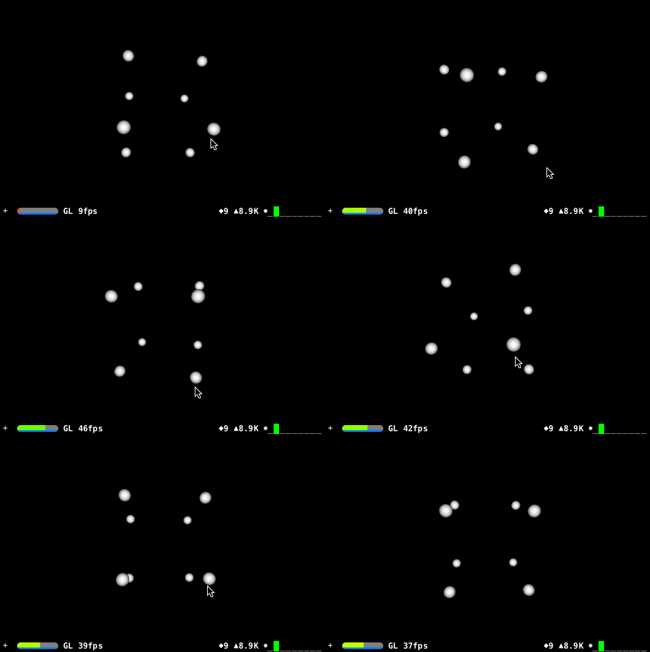
頂点座標だけソースとして渡しても何も表示されないので、とりあえずダミーとして各頂点に球体を配置します。
import UIKit
import SceneKit

class ViewController: UIViewController {
    override func loadView() {
        // シーンを表示するビューを準備します。
        let sceneView = SCNView()
        self.view = sceneView

        sceneView.backgroundColor = UIColor.blackColor()
        sceneView.autoenablesDefaultLighting = true
        sceneView.allowsCameraControl = true
        sceneView.showsStatistics = true

        // シーンを構築します。
        let scene = SCNScene()
        sceneView.scene = scene

        // カメラノードを追加します。
        let cameraNode = SCNNode()
        cameraNode.camera = SCNCamera()
        cameraNode.position = SCNVector3(x: 0, y: 0, z: 11)
        scene.rootNode.addChildNode(cameraNode)

        // 頂点を定義します。
        let half = Float(2)
        let vertices = [
            SCNVector3(-half, +half, +half), // 手前+左上 0
            SCNVector3(+half, +half, +half), // 手前+右上 1
            SCNVector3(-half, -half, +half), // 手前+左下 2
            SCNVector3(+half, -half, +half), // 手前+右下 3

            SCNVector3(-half, +half, -half), // 奥+左上 4
            SCNVector3(+half, +half, -half), // 奥+右上 5
            SCNVector3(-half, -half, -half), // 奥+左下 6
            SCNVector3(+half, -half, -half), // 奥+右下 7
        ]

        // カスタムジオメトリを作成します。
        let verticesSource = SCNGeometrySource(vertices: vertices, count: vertices.count)
        let customGeometry = SCNGeometry(sources: [verticesSource], elements: [])
        scene.rootNode.addChildNode(SCNNode(geometry: customGeometry))

        // 各頂点にダミーの球体を配置します。
        for vec in vertices {
            let node = SCNNode(geometry: SCNSphere(radius: 0.3))
            node.position = vec
            scene.rootNode.addChildNode(node)
        }
    }
}
ソースの通りですが、頂点の配列(8頂点)を定義した後、SCNGeometrySource(vertices: vertices, count: vertices.count)で頂点ソースを作成し、それをSCNGeometryのsources引数に渡しています。
面を貼る
今度は面の定義を行います。
SceneKit...というか大抵の3Dエンジンはポリゴン(三角形)しか描画ができないので、三角形を指定します。
指定の方法は2種類ありますが、今回は単純に「3つの頂点を複数個指定する方法」でやります。
class ViewController: UIViewController {
    override func loadView() {
        // シーンを表示するビューを準備します。
        let sceneView = SCNView()
        self.view = sceneView

        sceneView.backgroundColor = UIColor.blackColor()
        sceneView.autoenablesDefaultLighting = true
        sceneView.allowsCameraControl = true
        sceneView.showsStatistics = true

        // シーンを構築します。
        let scene = SCNScene()
        sceneView.scene = scene

        // カメラノードを追加します。
        let cameraNode = SCNNode()
        cameraNode.camera = SCNCamera()
        cameraNode.position = SCNVector3(x: 0, y: 0, z: 11)
        scene.rootNode.addChildNode(cameraNode)

        // 頂点を定義します。
        let half = Float(2)
        let vertices = [
            SCNVector3(-half, +half, +half), // 手前+左上 0
            SCNVector3(+half, +half, +half), // 手前+右上 1
            SCNVector3(-half, -half, +half), // 手前+左下 2
            SCNVector3(+half, -half, +half), // 手前+右下 3

            SCNVector3(-half, +half, -half), // 奥+左上 4
            SCNVector3(+half, +half, -half), // 奥+右上 5
            SCNVector3(-half, -half, -half), // 奥+左下 6
            SCNVector3(+half, -half, -half), // 奥+右下 7
        ]

        // ポリゴンを定義します。
        let indices: [Int32] = [
            // 手前
            0, 2, 1,
            1, 2, 3,

            // 奥
            4, 5, 7,
            4, 7, 6,

            // 左
            4, 6, 0,
            0, 6, 2,

            // 右
            5, 1, 3,
            5, 3, 7,

            // 上
            4, 0, 5,
            5, 0, 1,

            // 下
            6, 7, 2,
            7, 3, 2,
        ]

        // カスタムジオメトリを作成します。
        let verticesSource = SCNGeometrySource(vertices: vertices, count: vertices.count)
        let faceSource = SCNGeometryElement(indices: indices, primitiveType: .Triangles)
        let customGeometry = SCNGeometry(sources: [verticesSource], elements: [faceSource])
        scene.rootNode.addChildNode(SCNNode(geometry: customGeometry))

        // 各頂点にダミーの球体を配置します。
        for vec in vertices {
            let node = SCNNode(geometry: SCNSphere(radius: 0.3))
            node.position = vec
            scene.rootNode.addChildNode(node)
        }
    }
}
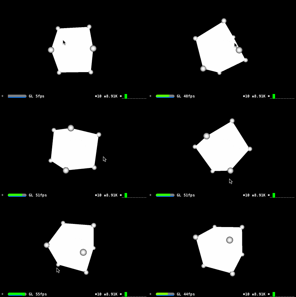
ポリゴンには向きが有り、標準では裏面はレンダリングされません(変更可能)。
各頂点を反時計回りに指定すると表面がこちらに見えるイメージです。
1面につき2ポリゴン必要ですので、12ポリゴンを定義しています。
なお、この頂点番号の指定はIntではなくInt32にする必要があります。
64bit端末でInt型にしてしまうと、Intは8バイト長になり、SceneKit側が対応できずにエラーとなります。
SCNGeometryElement(indices: indices, primitiveType: .Triangles)というように頂点番号の配列と、Trianglesという引数を渡してElementを生成します。
Trianglesを指定すると、配列の中の3つの値がポリゴンを成す事を指示します。
他にも頂点を共有するTriangleStripや直線を定義するLineなどが指定できます。
こうして生成した要素をSCNGeometryのelements引数に渡します。
うまく面が張れましたね。
光源処理されるようにする
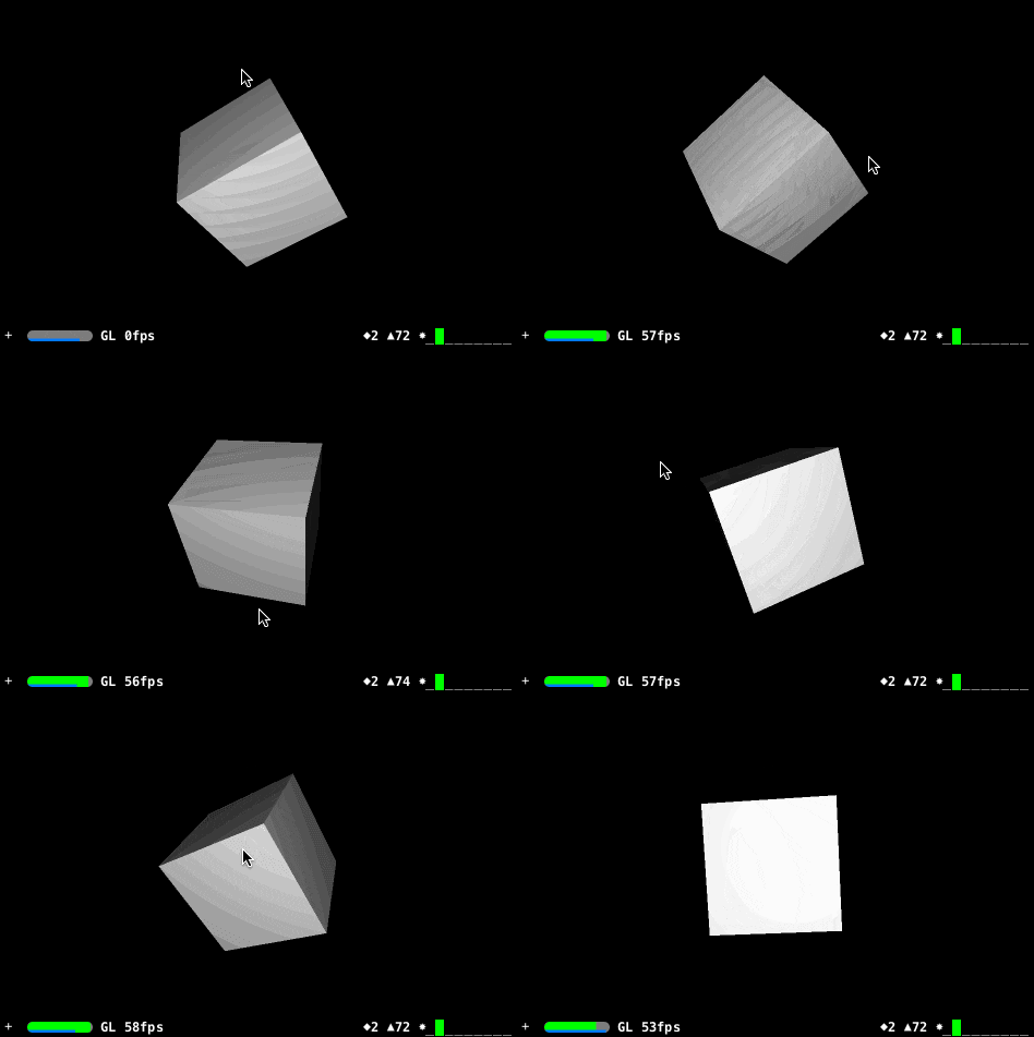
「何で色がのっぺりしてるのよ?」という事なんですが、これは法線ベクトルを一切指定していないからです。
法線ベクトルは一般的には面に垂直なベクトルの事を指し、この法線ベクトルと光源の逆ベクトルが成す角度が小さければ小さいほど明るくなる的な処理に使用されます。
今回のような立方体の場合、1ポリゴンに1つの法線ベクトルがあれば十分なはずなのですが、どうもSceneKitでは頂点毎に法線ベクトルを持つように決まっている(切り替え不可能?)ようで、「頂点の座標は同じだけど法線ベクトルは違う」なんて事が出来ないようなのです。
したがって、頂点の数(=法線ベクトルの数)も8ではなく、4×6=24個必要になります。
import UIKit
import SceneKit

class ViewController: UIViewController {
    override func loadView() {
        // シーンを表示するビューを準備します。
        let sceneView = SCNView()
        self.view = sceneView

        sceneView.backgroundColor = UIColor.blackColor()
        sceneView.autoenablesDefaultLighting = true
        sceneView.allowsCameraControl = true
        sceneView.showsStatistics = true

        // シーンを構築します。
        let scene = SCNScene()
        sceneView.scene = scene

        // カメラノードを追加します。
        let cameraNode = SCNNode()
        cameraNode.camera = SCNCamera()
        cameraNode.position = SCNVector3(x: 0, y: 0, z: 11)
        scene.rootNode.addChildNode(cameraNode)

        // 頂点を定義します。
        let half = Float(2)
        let vertices = [
            // 手前
            SCNVector3(-half, +half, +half), // 手前+左上 0
            SCNVector3(+half, +half, +half), // 手前+右上 1
            SCNVector3(-half, -half, +half), // 手前+左下 2
            SCNVector3(+half, -half, +half), // 手前+右下 3

            // 奥
            SCNVector3(-half, +half, -half), // 奥+左上 4
            SCNVector3(+half, +half, -half), // 奥+右上 5
            SCNVector3(-half, -half, -half), // 奥+左下 6
            SCNVector3(+half, -half, -half), // 奥+右下 7

            // 左側
            SCNVector3(-half, +half, -half), // 8 (=4)
            SCNVector3(-half, +half, +half), // 9 (=0)
            SCNVector3(-half, -half, -half), // 10 (=6)
            SCNVector3(-half, -half, +half), // 11 (=2)

            // 右側
            SCNVector3(+half, +half, +half), // 12 (=1)
            SCNVector3(+half, +half, -half), // 13 (=5)
            SCNVector3(+half, -half, +half), // 14 (=3)
            SCNVector3(+half, -half, -half), // 15 (=7)

            // 上側
            SCNVector3(-half, +half, -half), // 16 (=4)
            SCNVector3(+half, +half, -half), // 17 (=5)
            SCNVector3(-half, +half, +half), // 18 (=0)
            SCNVector3(+half, +half, +half), // 19 (=1)

            // 下側
            SCNVector3(-half, -half, +half), // 20 (=2)
            SCNVector3(+half, -half, +half), // 21 (=3)
            SCNVector3(-half, -half, -half), // 22 (=6)
            SCNVector3(+half, -half, -half), // 23 (=7)
        ]

        // 各頂点における法線ベクトルを定義します。
        let normals = [
            // 手前
            SCNVector3(0, 0, 1),
            SCNVector3(0, 0, 1),
            SCNVector3(0, 0, 1),
            SCNVector3(0, 0, 1),

            // 奥
            SCNVector3(0, 0, -1),
            SCNVector3(0, 0, -1),
            SCNVector3(0, 0, -1),
            SCNVector3(0, 0, -1),

            // 左側
            SCNVector3(-1, 0, 0),
            SCNVector3(-1, 0, 0),
            SCNVector3(-1, 0, 0),
            SCNVector3(-1, 0, 0),

            // 右側
            SCNVector3(1, 0, 0),
            SCNVector3(1, 0, 0),
            SCNVector3(1, 0, 0),
            SCNVector3(1, 0, 0),

            // 上側
            SCNVector3(0, 1, 0),
            SCNVector3(0, 1, 0),
            SCNVector3(0, 1, 0),
            SCNVector3(0, 1, 0),

            // 下側
            SCNVector3(0, -1, 0),
            SCNVector3(0, -1, 0),
            SCNVector3(0, -1, 0),
            SCNVector3(0, -1, 0),
        ]

        // ポリゴンを定義します。
        let indices: [Int32] = [
            // 手前
            0, 2, 1,
            1, 2, 3,

            // 奥
            4, 5, 7,
            4, 7, 6,

            // 左側
            8, 10, 9,
            9, 10, 11,

            // 右側
            13, 12, 14,
            13, 14, 15,

            // 上側
            16, 18, 17,
            17, 18, 19,

            // 下側
            22, 23, 20,
            23, 21, 20,
        ]

        // カスタムジオメトリを作成します。
        let verticesSource = SCNGeometrySource(vertices: vertices, count: vertices.count)
        let normalsSource = SCNGeometrySource(normals: normals, count: normals.count)
        let faceSource = SCNGeometryElement(indices: indices, primitiveType: .Triangles)
        let customGeometry = SCNGeometry(sources: [verticesSource, normalsSource], elements: [faceSource])
        scene.rootNode.addChildNode(SCNNode(geometry: customGeometry))
    }
}
頂点情報を増やし、それに対応させる形で法線ベクトルをnormals配列として定義(indicesの番号も変えます)。
SCNGeometrySource(normals: normals, count: normals.count)で法線ベクトルのソースを生成し、SCNGeometryクラスのsources配列に追記してやるだけです。
うまく陰が出るようになりましたね。
(GIFなので色が荒いですが...)
テクスチャ座標を指定する
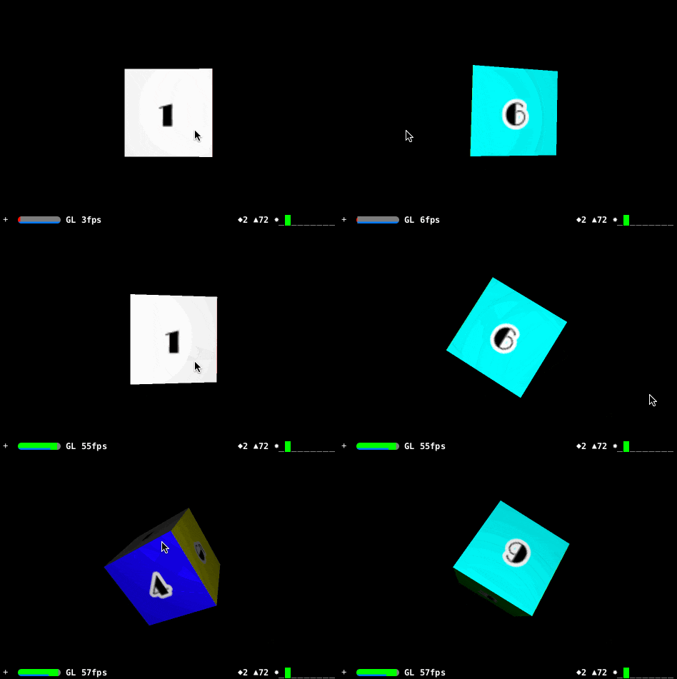
SceneKitの仕組み上、6枚の画像を各面に設定するという方法も簡単に可能ですが、今回は1枚のテクスチャを6面にマップしてみる事にします。
import UIKit
import SceneKit

class ViewController: UIViewController {
    override func loadView() {
        // シーンを表示するビューを準備します。
        let sceneView = SCNView()
        self.view = sceneView

        sceneView.backgroundColor = UIColor.blackColor()
        sceneView.autoenablesDefaultLighting = true
        sceneView.allowsCameraControl = true
        sceneView.showsStatistics = true

        // シーンを構築します。
        let scene = SCNScene()
        sceneView.scene = scene

        // カメラノードを追加します。
        let cameraNode = SCNNode()
        cameraNode.camera = SCNCamera()
        cameraNode.position = SCNVector3(x: 0, y: 0, z: 11)
        scene.rootNode.addChildNode(cameraNode)

        // 頂点を定義します。
        let half = Float(2)
        let vertices = [
            // 手前
            SCNVector3(-half, +half, +half), // 手前+左上 0
            SCNVector3(+half, +half, +half), // 手前+右上 1
            SCNVector3(-half, -half, +half), // 手前+左下 2
            SCNVector3(+half, -half, +half), // 手前+右下 3

            // 奥
            SCNVector3(-half, +half, -half), // 奥+左上 4
            SCNVector3(+half, +half, -half), // 奥+右上 5
            SCNVector3(-half, -half, -half), // 奥+左下 6
            SCNVector3(+half, -half, -half), // 奥+右下 7

            // 左側
            SCNVector3(-half, +half, -half), // 8 (=4)
            SCNVector3(-half, +half, +half), // 9 (=0)
            SCNVector3(-half, -half, -half), // 10 (=6)
            SCNVector3(-half, -half, +half), // 11 (=2)

            // 右側
            SCNVector3(+half, +half, +half), // 12 (=1)
            SCNVector3(+half, +half, -half), // 13 (=5)
            SCNVector3(+half, -half, +half), // 14 (=3)
            SCNVector3(+half, -half, -half), // 15 (=7)

            // 上側
            SCNVector3(-half, +half, -half), // 16 (=4)
            SCNVector3(+half, +half, -half), // 17 (=5)
            SCNVector3(-half, +half, +half), // 18 (=0)
            SCNVector3(+half, +half, +half), // 19 (=1)

            // 下側
            SCNVector3(-half, -half, +half), // 20 (=2)
            SCNVector3(+half, -half, +half), // 21 (=3)
            SCNVector3(-half, -half, -half), // 22 (=6)
            SCNVector3(+half, -half, -half), // 23 (=7)
        ]

        // 各頂点におけるテクスチャ座標を定義します。
        let texcoords = [
            // 手前
            float2(0, 0),
            float2(1 / 6, 0),
            float2(0, 1),
            float2(1 / 6, 1),

            // 奥
            float2(1, 0),
            float2(5 / 6, 0),
            float2(1, 1),
            float2(5 / 6, 1),

            // 左側
            float2(1 / 6, 0),
            float2(2 / 6, 0),
            float2(1 / 6, 1),
            float2(2 / 6, 1),

            // 右側
            float2(4 / 6, 0),
            float2(5 / 6, 0),
            float2(4 / 6, 1),
            float2(5 / 6, 1),

            // 上側
            float2(2 / 6, 0),
            float2(3 / 6, 0),
            float2(2 / 6, 1),
            float2(3 / 6, 1),

            // 下側
            float2(3 / 6, 0),
            float2(4 / 6, 0),
            float2(3 / 6, 1),
            float2(4 / 6, 1),
        ]

        // 各頂点における法線ベクトルを定義します。
        let normals = [
            // 手前
            SCNVector3(0, 0, 1),
            SCNVector3(0, 0, 1),
            SCNVector3(0, 0, 1),
            SCNVector3(0, 0, 1),

            // 奥
            SCNVector3(0, 0, -1),
            SCNVector3(0, 0, -1),
            SCNVector3(0, 0, -1),
            SCNVector3(0, 0, -1),

            // 左側
            SCNVector3(-1, 0, 0),
            SCNVector3(-1, 0, 0),
            SCNVector3(-1, 0, 0),
            SCNVector3(-1, 0, 0),

            // 右側
            SCNVector3(1, 0, 0),
            SCNVector3(1, 0, 0),
            SCNVector3(1, 0, 0),
            SCNVector3(1, 0, 0),

            // 上側
            SCNVector3(0, 1, 0),
            SCNVector3(0, 1, 0),
            SCNVector3(0, 1, 0),
            SCNVector3(0, 1, 0),

            // 下側
            SCNVector3(0, -1, 0),
            SCNVector3(0, -1, 0),
            SCNVector3(0, -1, 0),
            SCNVector3(0, -1, 0),
        ]

        // ポリゴンを定義します。
        let indices: [Int32] = [
            // 手前
            0, 2, 1,
            1, 2, 3,

            // 奥
            4, 5, 7,
            4, 7, 6,

            // 左側
            8, 10, 9,
            9, 10, 11,

            // 右側
            13, 12, 14,
            13, 14, 15,

            // 上側
            16, 18, 17,
            17, 18, 19,

            // 下側
            22, 23, 20,
            23, 21, 20,
        ]

        // カスタムジオメトリを作成します。
        let verticesSource = SCNGeometrySource(vertices: vertices, count: vertices.count)
        let normalsSource = SCNGeometrySource(normals: normals, count: normals.count)
        let texcoordSource = SCNGeometrySource(textureCoordinates: texcoords)
        let faceSource = SCNGeometryElement(indices: indices, primitiveType: .Triangles)
        let customGeometry = SCNGeometry(sources: [verticesSource, normalsSource, texcoordSource], elements: [faceSource])

        // テクスチャ画像を指定します。
        let material = SCNMaterial()
        material.diffuse.contents = UIImage(named: "texture")
        customGeometry.materials = [material]

        scene.rootNode.addChildNode(SCNNode(geometry: customGeometry))
    }
}

extension SCNGeometrySource {
    convenience init(textureCoordinates texcoord: [float2]) {
        let data = NSData(bytes: texcoord, length: sizeof(float2) * texcoord.count)
        self.init(data: data, semantic: SCNGeometrySourceSemanticTexcoord, vectorCount: texcoord.count, floatComponents: true, componentsPerVector: 2, bytesPerComponent: sizeof(Float), dataOffset: 0, dataStride: sizeof(float2))
    }
}
流れとしては、「頂点におけるテクスチャ座標」の配列(texcoords)を用意し、そこからSCNGeometrySourceを作るというお馴染みのパターンなのですが、ここで一つ罠があります。
公式のコンビニエンスイニシャライザが用意されているのですが、
public convenience init(textureCoordinates texcoord: UnsafePointer<CGPoint>, count: Int)
ご覧の通りCGPoint型を受け取るようになっていまして、これが例によって64bit環境だとDouble型になるためSceneKitがエラーを吐きます。
そのうち修正されるのではないかと思うのですが。
そのため、CGPointではなくfloat2という丁度良さそうな型で代用しています。
専用のコンビニエンスイニシャライザconvenience init(textureCoordinates texcoord: [float2])を定義しているのはそのためです。
うまくテクスチャマッピングできましたね。
おまけ SCNVector3をアフィン変換するには
CGPointで言うところのCGPointApplyAffineTransformみたいなやつのSCNVector3版が見当たらなかったので作ってみました。
func SCNVector3ApplyAffineTransform(vector: SCNVector3, _ t: SCNMatrix4) -> SCNVector3 {
    let x = vector.x * t.m11 + vector.y * t.m21 + vector.z * t.m31 + t.m41
    let y = vector.x * t.m12 + vector.y * t.m22 + vector.z * t.m32 + t.m42
    let z = vector.x * t.m13 + vector.y * t.m23 + vector.z * t.m33 + t.m43
    return SCNVector3Make(x, y, z)
}


