前回に続き、NefryでGroveの照度センサを使ってみます。
Grove - Luminance Sensor
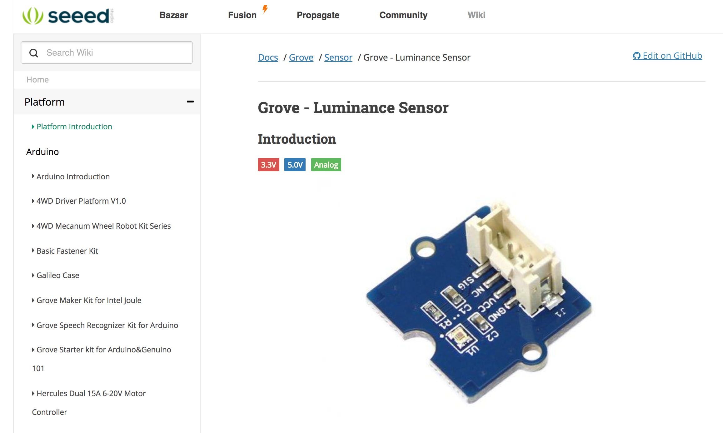
スペックはこんな感じです。 Nefryだと3.3V対応しているセンサを使えるのでこのセンサーは問題なく使えます。
Parameter	Value
Vcc	2.4V ~ 5.5V
Linear output range	0.0 ~ 2.3V
Luminance measurement range	0 ~ 1000 Lux
暗くなったらライトがつく(明るくなる)街灯っぽいものをつくる
明るさに反応するものを作ります。
Arduinoのサンプルプログラムに毛が生えたくらいですが以下がプログラムになります。
ライブラリを使いたかったのですがエラーが出てひよったのでとりあえず動くものを作りました。
#include <Nefry.h>

float VoutArray[] =  { 0.0011498,  0.0033908,   0.011498, 0.041803,0.15199,     0.53367, 1.3689,   1.9068,  2.3};
float LuxArray[] =  { 1.0108,     3.1201,  9.8051,   27.43,   69.545,   232.67,  645.11,   73.52,  1000};

void setup() {
  Nefry.println("Grove Luminance Sensor !");
  Nefry.setLed(0,0,0);
}

void loop() {
    Nefry.print("Vout =");
    Nefry.print(readAPDS9002Vout(A0));
    Nefry.print(" V,Luminance =");
    Nefry.print(readLuminance(A0));
    Nefry.println("Lux");
    float val = 255;
    val = val - (readLuminance(A0) * 2);
    Nefry.println(val);
    Nefry.setLed(200,200,0,val);
    Nefry.ndelay(500);
}

float readAPDS9002Vout(uint8_t analogpin)
{
    // MeasuredVout = ADC Value * (Vcc / 1023) * (3 / Vcc)
    // Vout samples are with reference to 3V Vcc
    // The above expression is simplified by cancelling out Vcc
    float MeasuredVout = analogRead(A0) * (3.0 / 1023.0);
    //Above 2.3V , the sensor value is saturated

    return MeasuredVout;

}

float readLuminance(uint8_t analogpin)
{

    // MeasuredVout = ADC Value * (Vcc / 1023) * (3 / Vcc)
    // Vout samples are with reference to 3V Vcc
    // The above expression is simplified by cancelling out Vcc
    float MeasuredVout = analogRead(A0) * (3.0 / 1023.0);
    float Luminance = FmultiMap(MeasuredVout, VoutArray, LuxArray, 9);

    /**************************************************************************

    The Luminance in Lux is calculated based on APDS9002 datasheet -- > Graph 1
    ( Output voltage vs. luminance at different load resistor)
    The load resistor is 1k in this board. Vout is referenced to 3V Vcc.

    The data from the graph is extracted using WebPlotDigitizer
    http://arohatgi.info/WebPlotDigitizer/app/

    VoutArray[] and LuxArray[] are these extracted data. Using MultiMap, the data
    is interpolated to get the Luminance in Lux.

    This implementation uses floating point arithmetic and hence will consume
    more flash, RAM and time.

    The Luminance in Lux is an approximation and depends on the accuracy of
    Graph 1 used.

    ***************************************************************************/

    return Luminance;
}


//This code uses MultiMap implementation from http://playground.arduino.cc/Main/MultiMap

float FmultiMap(float val, float * _in, float * _out, uint8_t size)
{
    // take care the value is within range
    // val = constrain(val, _in[0], _in[size-1]);
    if (val <= _in[0]) return _out[0];
    if (val >= _in[size-1]) return _out[size-1];

    // search right interval
    uint8_t pos = 1;  // _in[0] allready tested
    while(val > _in[pos]) pos++;

    // this will handle all exact "points" in the _in array
    if (val == _in[pos]) return _out[pos];

    // interpolate in the right segment for the rest
    return (val - _in[pos-1]) * (_out[pos] - _out[pos-1]) / (_in[pos] - _in[pos-1]) + _out[pos-1];
}