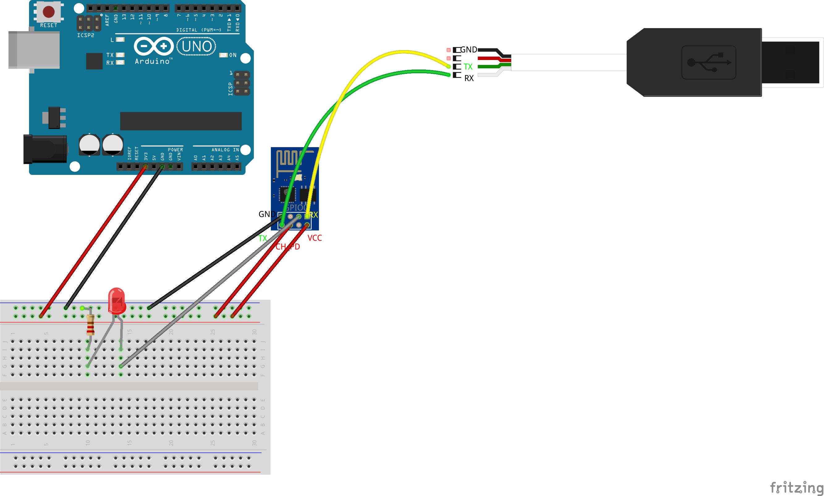
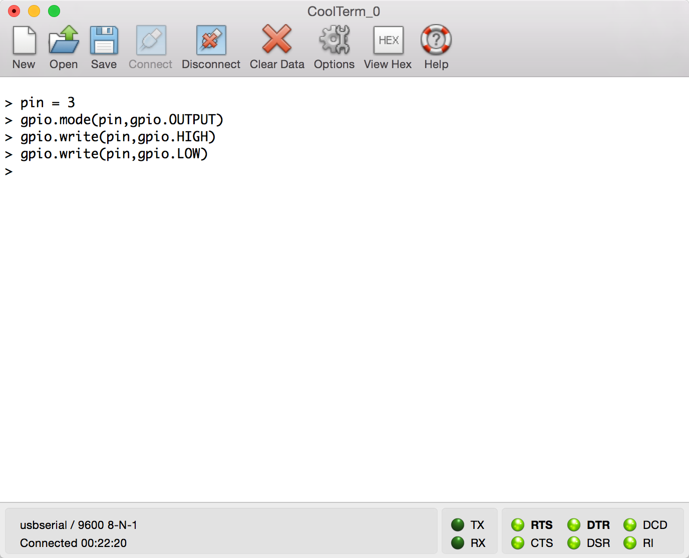
NodeMCUのファームウェアをアップロードしたESP8266をホストマシンとUSB-TTLシリアル接続します。シリアル通信はCoolTermから操作します。ArduinoをESP8266への3.3Vの電源供給用です。NodeMCUを使うとESP8266単体でLuaを使ったハードウェア制御ができるようになります。
Wi-Fiの設定
最初にアクセスポイントの設定をします。NodMCUをファームウェアにしたESP8266は既存の無線LANの子機として動作させます。wifi.sta.configにはアクセスポイントのSSIDとパスワードを指定します。DHCPからIPアドレスが取得できました。
> wifi.setmode(wifi.STATION)
> wifi.sta.config("{SSID}","{Password}")
> = wifi.sta.status()
5 GOT IP
> = wifi.sta.getip()
192.168.1.16	255.255.255.0	192.168.1.1
>
HTTPクライアント
次にNodeMCUをHTTPクライアントとして使ってみます。Node.jsのようにイベント駆動なコールバックを定義して受信したpayloadを出力します。この例ではNodeMCUのホームページのHTMLを取得します。
> conn = net.createConnection(net.TCP, false)
> conn:on("receive", function(conn, payload) print(payload) end)
> conn:connect(80,"121.41.33.127")
> conn:send("GET / HTTP/1.1\r\nHost: www.nod`mcu.com\r\n"
>> .."Connection: keep-alive\r\nAccept: */*\r\n\r\n")
Lチカ
配線図のようにLEDをESP8266のGPIO0につなぎます。USB-TTLシリアル変換モジュールのVCCが5Vなので、Arduino Unoを3.3V電源供給用に使います。
ESP8266のGPIOピンアサインを見るとGPIO0はPin 3になります。CoolTermから以下のように実行します。Arduinoと似た感じでHIGHでLEDが点灯し、LOWで消灯します。
> pin = 3
> gpio.mode(pin,gpio.OUTPUT)
> gpio.write(pin,gpio.HIGH)
> gpio.write(pin,gpio.LOW)

