はじめに
Partial Reconfiguration とは
Partial Reconfiguration とは FPGA の一部を(他の部分は生かしたまま)書き換える技術です。この記事では Xilinx社の Vivado で Partial Reconfiguration を使うためのデザインフローを紹介します。
Partial Reconfiguration の利点
従来の Full Reconfiguration では FPGA を書き換えるためには一度FPGA 全体をリセットしてFPGA全体のビットストリームをダウンロードする必要があります。この書き換え期間中は FPGA 自体がダウンロードモードに入っているため、例えば外部にディスプレイや外部機器があっても動作させることはできません。
FPGA の規模が大きくなるにつれて、一つのFPGA内に複数の機能を入れることが多くなりました。しかし Full Reconfiguration では一部の機能だけを動的に切り替えたくても FPGA 全体がダウンロードモードになるので他の機能も使えなくなってしまいます。例えて言うなら、パソコンのアプリケーションを切り替える度にパソコンを再起動しているような状態です。
Partial Reconfiguration を使うことにより、他の機能を動作させたまま、一部の機能だけを動的に切り替えることができます。Partial Reconfiguration によって FPGA がより便利になることでしょう。
Partial Reconfiguration の現状
現状、Partial Reconfiguration を行うのはそれほど簡単ではありません。従来の FPGA の設計技術に加えて、クロックやリセットの制御さらにインターフェースのデカップリングの知見がハードウェアとソフトウェアの双方で必要です。
しかし最近は次のように環境が整備されつつあります。
- Vivado 2017.1 より Design Edition または System Edition(要購入40万円くらい)に Partial Reconfiguration ライセンスが無償で追加された
-
Vivado 2017.1 より WebPack版(無償)には Partial Reconfiguration ライセンスが有償(10万円くらい)で追加可能になった
Vivado 2019.1 より WebPack版(無償)には Partial Reconfiguration ライセンスが無償になった - Xilinx が AXI 用の Partial Reconfiguration Decouple IP を提供するようになった
- Linux Kernel 4.10 から正式にデバイスドライバで Partial Reconfiguration をサポートするようになった
- Linux Kernel 4.11 から Xilinx の AXI 用の Partial Reconfiguration Decouple IP のデバイスドライバが追加された
Partial Reconfiguration 開発環境
ここでは以下の環境でのデザインフローの説明をします。
- Vivado 2017.2 WebPACK版
- Partial Reconfiguration 有償ライセンス
Partial Reconfiguration のデザインフロー
デザインフローの種類
Vivado で Partial Reconfiguration のデザインをする場合、次の2種類の方法があります。
1. Vivado Partial Reconfiguration ツールフロー
これは従来の Vivado がサポートしていたデザインフローです。最近は次で説明するプロジェクトフローと対比させるためでしょうか、非プロジェクトフローとも言われています。このデザインフローは Design Checkpoint と Tcl スクリプトをベースにしています。
Design Checkpoint に関しては「Vivado の Design Checkpoint とは」に詳しく説明しています。そちらを参照してください。
GUI からの操作は限定的で主に Tcl スクリプトを Vivado に実行させることで各種操作を行います。
2. Vivado Partial Reconfiguration プロジェクトフロー
これは比較的新しい(Vivado 2017.1あたり)から新たに追加されたデザインフローです。Vivado のプロジェクトをベースにしており、GUI から操作できるのが特徴です。最近出ただけあって、すこし機能的な制限があることと、取り切れていないであろうバグ(地雷)の存在が心配です。
デザインフローの基本
前節の紹介したように Vivado で Parital Reconfiguration のデザインをする場合、2種類のデザインフローがあります。しかし双方のデザインフローも基本的にやっていることは変わりません。ここではその基本的なことについて説明します。
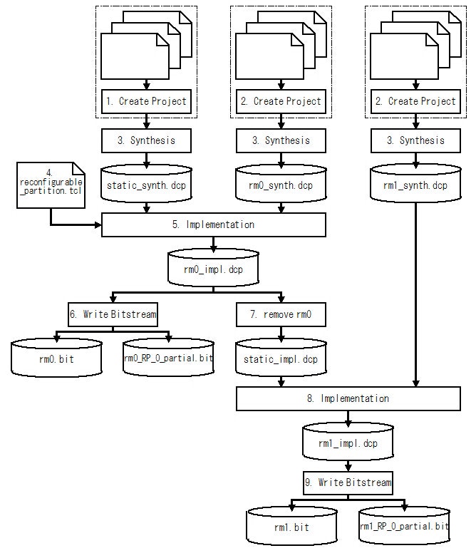
基本的に Partial Reconfiguration のデザインフローは次のようになっています。
- ベースとなる部分(Static Module)を RTL や Vivado の IP Integrator などでデザインする
- Partial Reconfiguration したい部分(Reconfigurable Module)をRTL や Vivado の IP Integrator などでデザインする
- Static Module と Reconfigurable Moduleを各々論理合成する
- Reconfigurable Module の FPGA 上の領域(Reconfigurable Partition)を決める
- Static Module と Reconfigurable Module の一つをリンクして配置配線する
- 5.の配置配線結果から bitstream を作る
- 5.の配置配線結果から Reconfigurable Module を削除して Static Module の配置配線結果を固定した Design Checkpoint をつくる
- 7.で作った Design Checkpoint に 別の Reconfigurable Module をリンクして配置配線をする
- 7.の配置配線結果から bitstream をつくる
上記のデザインフローを図で示すと Fig.1 のようになります。
Fig.1 Partial Reconfiguration の基本的なデザインフロー
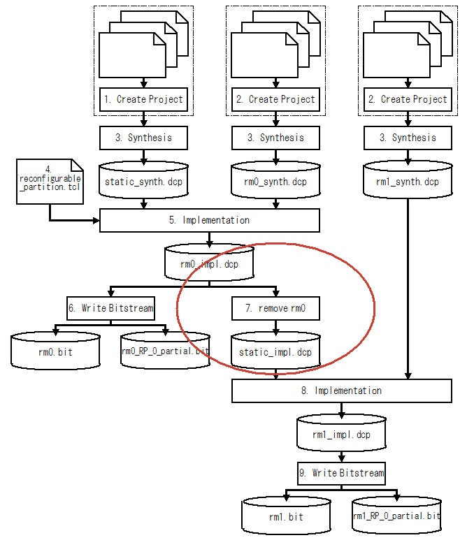
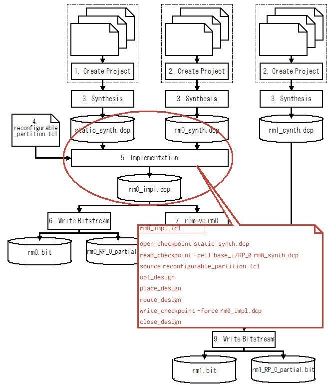
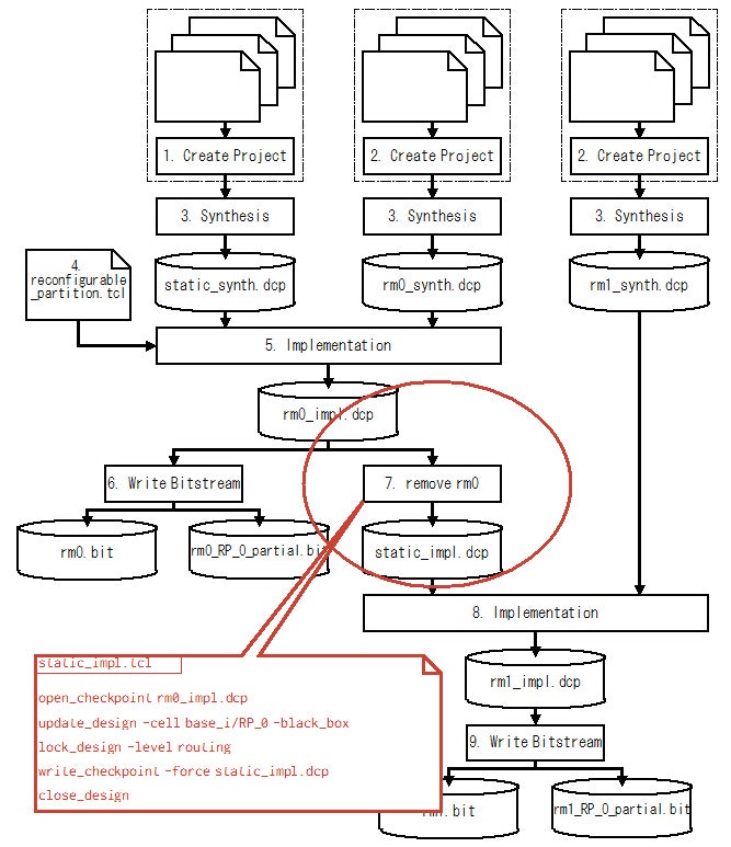
このデザインフローでちょっと特殊な部分が、7.の工程でしょう(Fig.2 の赤丸部分)。
Fig.2 Partial Reconfiguration デザインフローのちょっと特殊な工程
基本的に FPGA の Partial Reconfiguration のデザインフローでは、まず Static Moduleと何か一つ Reconfigurable Module を組み合わせた状態で一度配置配線を実行します(工程5)。それから Reconfigurable Module を削除して、Static Module のリソース(LUTやFFの位置情報や配線情報)を固定したものを用意します(工程7)。ちなみにこの情報を Amazon EC2 F1 ではシェル(殻)と呼んでいるようです。
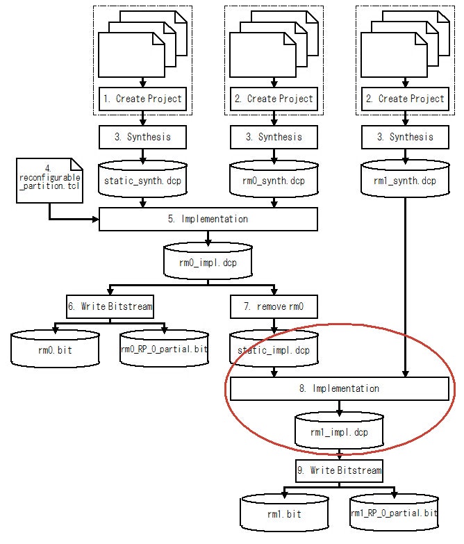
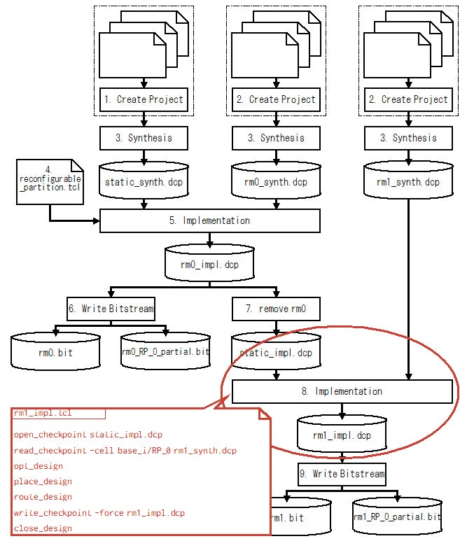
別の Reconfigurable Module を配置配線して Bitstream を作るには、この配置配線済みStatic Module の Design Checkpoint(static_impl.dcp)を利用します(Fig.3 の赤丸部分)。
Fig.3 Partial Reconfiguration デザインフローの Reconfigurable Module の配置配線工程
具体的には配置配線済みStatic Module のDesign Checkpoint と Reconfigurable Module を論理合成した Design Checkpoint をリンクして配置配線を実行します(工程8)。すると、Static Moduleの部分はすでに配置配線が済んでいるので、新たにリンクされたReconfigurable Module のみがReconfiurable Partition 内に配置配線されます。
ここで重要なことは、Reconfigurable Module の Bitstream を作るためには、Static Module を配置配線したDesign Checkpoint が必要なことです。これは、なんらかの事情で Static Module の配置配線をやり直した場合、たとえ論理的には変更が無かった場合でも、必ず全ての Reconfigurable Module の Bitstream を作り直さなければならないことを意味します。
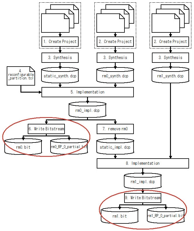
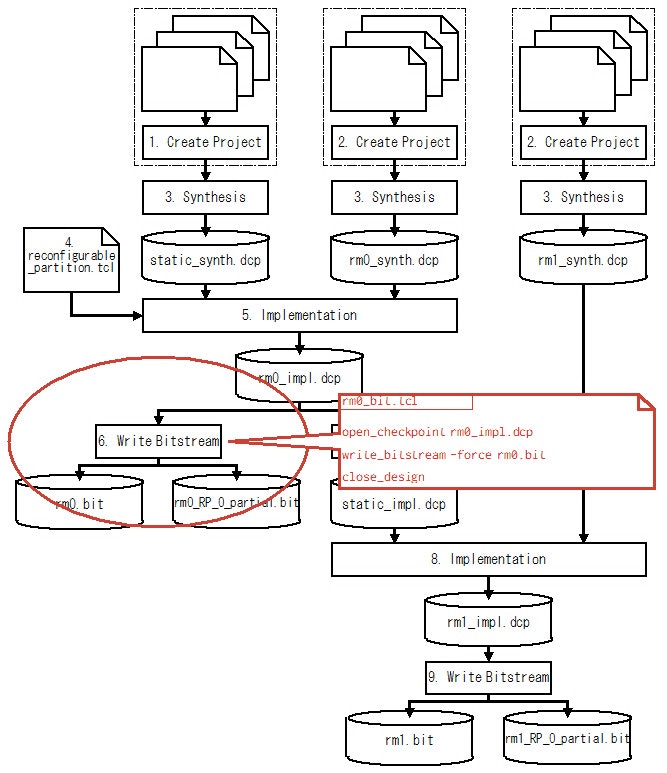
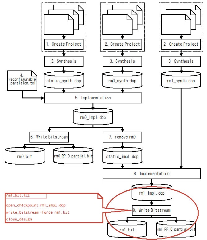
さらに Bitstream の生成も通常の FPGA のデザインフローと異なります(Fig.4 の赤丸部分)。
Fig.4 Partial Reconfiguration デザインフローのビットストリーム生成工程
具体的には、 FPGA 全体の Bitstream とは別に、各 Reconfigurable Partition 毎その部分だけの Bitstream が自動的に生成されます。例えば Fig.4 では工程6で、FPGA 全体の Bitstream ファイル(rm0.bit)の他に、Reconfigurable Partition の部分だけを取り出した Bitstreamファイル(rm0_RP_0_partial.bit)が生成されます。
- FPGA 全体を Full Reconfiguration する場合は、FPGA 全体の Bitstream ファイル(rm0.bit)を使います。
- Reconfigurable Partition をReconfigurable Module(rm0) の内容で Partial Reconfiguration する場合はReconfigurable Partition の部分だけを取り出した Bitstreamファイル(rm0_RP_0_partial.bit)を使います。
- Reconfigurable Partition をReconfigurable Module(rm1) の内容で Partial Reconfiguration する場合はReconfigurable Partition の部分だけを取り出した Bitstreamファイル(rm1_RP_0_partial.bit)を使います。
Vivado Partial Reconfiguration ツールフローの詳細
ここではDesign Checkpoint と Tcl スクリプトをベースにした Vivado Parital Reconfiguration ツールフローについて、実際のTclスクリプトを使って少し詳細に説明します。
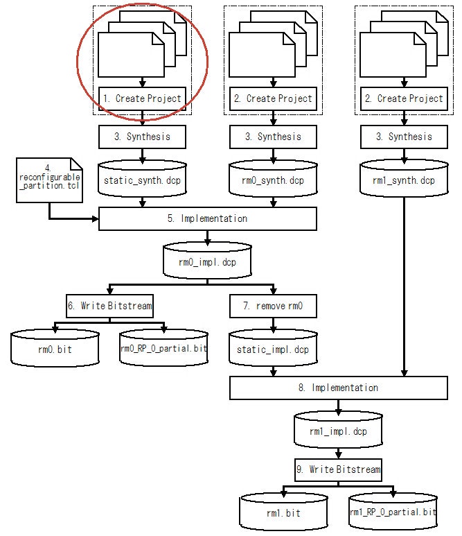
1. Static Module のデザイン
Static Module は通常通り RTL や Vivado IP Integrater を使ってデザインできます。ただし、デザインする上で Partial Reconfiguration 用にいくつか注意する点があります。具体的には、クロックの制御、リセットの制御、Reconfigurable Module と Static Module の間のインターフェースの制御が必要です。これらの注意点については別途、記事にする予定です。
Fig.5 Static Module のデザイン
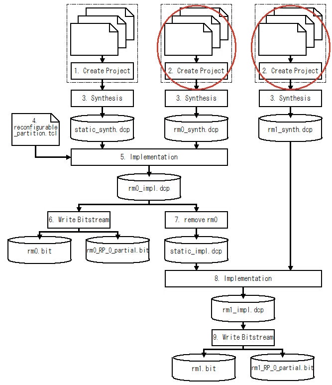
2. Reconfigurable Module のデザイン
Reconfigurable Module は通常通り RTL や Vivado IP Integrater を使ってデザインできます。ただし、 Static Module と同様に、デザインする上で Partial Reconfiguration 用にいくつか注意する点があります。これらの注意点については別途、記事にする予定です。
Fig.6 Reconfigurable Module のデザイン
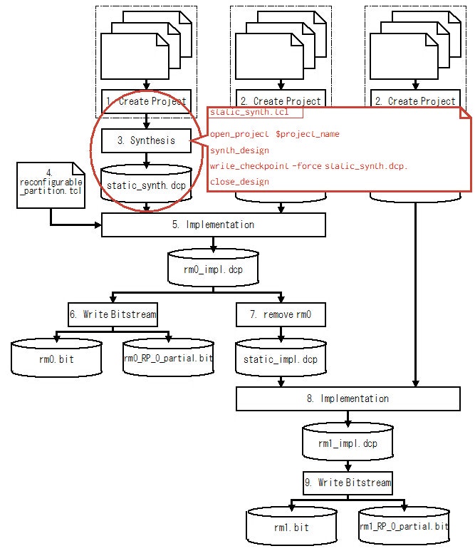
3-1. Static Module の論理合成
Static Module の論理合成は Tcl スクリプトの synth_design コマンドを使います。
Fig.7 Static Module の論理合成
open_project  $project_name
synth_design
write_checkpoint -force static_synth.dcp.
close_design
または Vivado の launch を使って論理合成します。
open_project $project_name
launch_runs synth_1
wait_on_run synth_1
open_run synth_1 -name synth_1
write_checkpoint -force static_synth.dcp
close_design
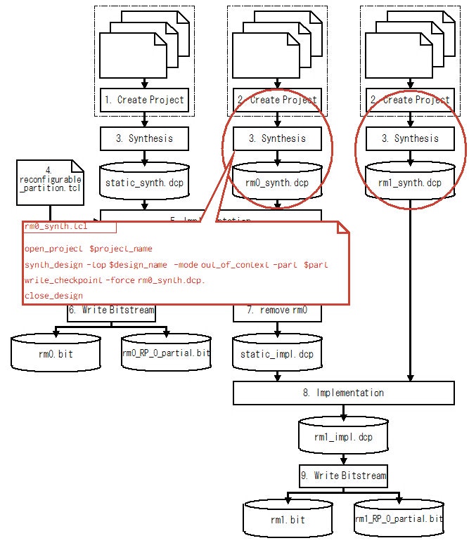
3-2 Reconfigurable Module の論理合成
Reconfigurable Module の論理合成は Tcl スクリプトの synth_design コマンドを使います。
Fig.8 Reconfigurable Module の論理合成
open_project  $project_name
synth_design -top $design_name  -mode out_of_context -part  $part
write_checkpoint -force rm0_synth.dcp.
close_design
または Vivado の launch を使って論理合成します。
open_project $project_name
set_property -name {STEPS.SYNTH_DESIGN.ARGS.MORE OPTIONS} \\
                   -value {-mode out_of_context} -objects [get_runs synth_1]
launch_runs synth_1
wait_on_run synth_1
open_run synth_1 -name synth_1
write_checkpoint -force rm0_synth.dcp
close_design
論理合成時にオプションとして out_of_context を指定します。この out_of_context を指定することによって Vivado はI/Oバッファを挿入しないようになります。
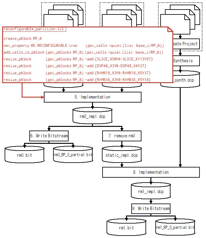
4. Reconfigurable Partitionの設定
FPGA 上での Reconfigurable Partition の位置情報を指定します。
Fig.9 Reconfigurable Partitionの設定
なお、Reconfigurable Partition の設定は、いろいろと面倒な決まり事があります。ここでは設定の一例を紹介するに留め、詳細はまた別途説明したいと思います。
この例では、ベースとなるシステムの中の Reconfigurable Module のインスタンス(base_i/RP_0)に対してHD.RECONFIGURABLE プロパティを TRUE にすることによって base_i/RP_0が Reconfigurable Module であることを指定しています。
さらに、create_pblock コマンドで pblock (多分 Partition Block の略) を作ります。作った pblock に対して、 add_cells_to_pblock コマンドでインスタンス(Xilinx では cell と呼んでいる)を対応付けし、resize_pblock コマンドで FPGA 上の領域を設定しています。
create_pblock RP_0
set_property HD.RECONFIGURABLE true      [get_cells -quiet [list  base_i/RP_0]]
add_cells_to_pblock [get_pblocks RP_0] [get_cells -quiet [list  base_i/RP_0]]
resize_pblock          [get_pblocks RP_0] -add {SLICE_X50Y0:SLICE_X113Y97}
resize_pblock          [get_pblocks RP_0] -add {DSP48_X3Y0:DSP48_X4Y37}
resize_pblock          [get_pblocks RP_0] -add {RAMB18_X3Y0:RAMB18_X5Y37}
resize_pblock          [get_pblocks RP_0] -add {RAMB36_X3Y0:RAMB36_X5Y18}
5. Static Module + Reconfigurable Module の配置配線
Static Module と Reconfigurable Module の一つをリンクして配置配線しています。
Fig.10 Static Module + Reconfigurable Module の配置配線
open_checkpoint static_synth.dcp
read_checkpoint -cell base_i/RP_0 rm0_synth.dcp
source reconfigurable_partition.tcl
opt_design
place_design
route_design
write_checkpoint -force rm0_impl.dcp
close_design
ここで生成した Design Checkpoint は Reconfigurable Module だけでなく Static Module を含んだ FPGA 全体の配置配線情報が含まれていることに注意してください。
6. Full Reconfiguration と Reconfigurable Module の Bitstream の生成
write_bitstream コマンドを使って Bitstream を生成します。
Fig.11 Full Reconfiguration と Reconfigurable Module の Bitstream の生成
write_bitstream コマンドは、pblock が定義されていると、Full Reconfiguration 用の Bitstream ファイルの他に、pblock毎に <base_name>_<pblock_name>_partial.bit という名前の Partial Reconfiguration 用の Bitstream ファイルを生成します。
open_checkpoint rm0_impl.dcp
write_bitstream -force rm0.bit
close_design
7. 配置配線済みStatic Module の Design Checkpoint の生成
他の Reconfigurable Module を配置配線するために使用する Static Module 部のみを配置配線した Design Checkpoint を生成します。
Fig.12 配置配線済みStatic Module の Design Checkpoint の生成
update_design コマンドに -black_box オプションを指定して、Reconfigurable Module のインスタンス(cell)を デザインから削除します。
さらに lock_design コマンドを使って、残りの Static Module 部の配置配線を固定(ロック)します。
open_checkpoint rm0_impl.dcp
update_design -cell base_i/RP_0 -black_box
lock_design -level routing
write_checkpoint -force static_impl.dcp
close_design
8. Reconfigurable Module の配置配線
工程7 で作成した 配置配線済みStatic Module の Design Checkpoint を使って、残りの Reconfigurable Module の配置配線を行います。
Fig.13 Reconfigurable Module の配置配線
open_checkpoint static_impl.dcp
read_checkpoint -cell base_i/RP_0 rm1_synth.dcp
opt_design
place_design
route_design
write_checkpoint -force rm1_impl.dcp
close_design
9. Reconfigurable Module の Bitstream の生成
write_bitstream コマンドを使って Bitstream を生成します。この工程は6の工程と同じです。
Fig.14 Reconfigurable Module の Bitstream の生成
open_checkpoint rm1_impl.dcp
write_bitstream -force rm1.bit
close_design
Vivado Partial Reconfiguration プロジェクトフローの詳細
プロジェクトフローに関しては、まだ試していないのであとで追記する予定です。
