ESP-WROOM-02 は単体で Arduino として使用できます。
Arduino のWireライブラルを使用すると I2C 制御が簡単にできるので紹介します。
回路図
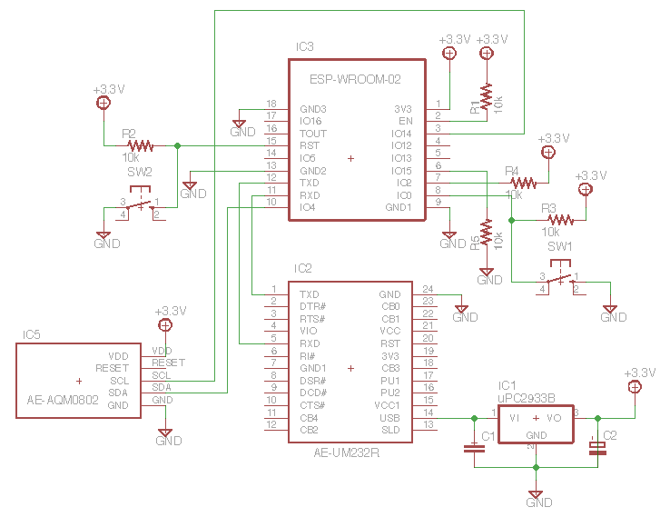
必要なもの
- ESP-WROOM-02
私は926円で買いました。安い! - FT232RL USBシリアル変換モジュール AE-UM232R
http://akizukidenshi.com/catalog/g/gK-01977/
ESP-WROOM-02 と Arduino をシリアル通信するために使用します - I2C接続小型キャラクタLCDモジュール 8x2行 AE-AQM0802
http://akizukidenshi.com/catalog/g/gP-06669/
このデバイスを I2C で制御します - I2C接続小型LCDモジュール用ピッチ変換基板
http://akizukidenshi.com/catalog/g/gP-06794/ - 3.3V 3端子レギュレータ
出力が 3.3V ならなんでもいいのですが uPC2933B を使いました。
ちなみに AE-UM232R にも 3.3V の出力端子ありますが、最大定格が 50mA しかないのでこれで 3.3V を作ります。 - 抵抗10kΩ x5
- セラミックコンデンサ 0.1uF x2
- アルミ電解コンデンサ 10uF
- PC
Arduino 環境をインストール済みのPC。
わたしは Mac を使いましたが、Windows, Linux も環境あるようです。
Arduino 環境のインストール方法は https://github.com/esp8266/Arduino の Installing with Boards Manager に書いてあります。 - ブレッドボード
長めなブレッドボードでないと入りきりません
スケッチ
esp-wroom-02-i2c.ino
# include <Wire.h>
# define ADDR 0x3e

void setup() {
  Serial.begin(115200);
  delay(10);
  Serial.println("");
  Serial.println("Started");
  Wire.begin(4, 14);
  delay(40);

  uint8_t cmd_init[] = {0x38, 0x39, 0x14, 0x70, 0x56, 0x6c, 0x38, 0x0d, 0x01};
  command(cmd_init, sizeof(cmd_init));
  delayMicroseconds(1080);  // 1.08ms

  uint8_t cmd_str1[] = {0x48, 0x65, 0x6c, 0x6c, 0x6f};
  uint8_t cmd_cr[] = {0xc0};
  uint8_t cmd_str2[] = {0x57, 0x6f, 0x72, 0x6c, 0x64, 0x21};
  write(cmd_str1, sizeof(cmd_str1));
  command(cmd_cr, sizeof(cmd_cr));
  write(cmd_str2, sizeof(cmd_str2));
}

void loop() {
}

void command(uint8_t *cmd, size_t len) {
  size_t i;
  for (i=0; i<len; i++) {
    Wire.beginTransmission(ADDR);
    Wire.write(0x00);
    Wire.write(cmd[i]);
    Wire.endTransmission();
    delayMicroseconds(27);    // 26.3us
  }
}

void write(uint8_t *cmd, size_t len) {
  size_t i;
  for (i=0; i<len; i++) {
    Wire.beginTransmission(ADDR);
    Wire.write(0x40);
    Wire.write(cmd[i]);
    Wire.endTransmission();
    delayMicroseconds(27);    // 26.3us
  }
}
ファームウェアの書き込み方
- sw1 を押しながら sw2 を押します。その後 sw1 を離します。
sw2 を離すときに sw1 が押されていればOKです。
IO1 を Low にしてリセットすることで、ファームウェア書き込みモードで起動しているのです。 - Arduino でスケッチを開きます
- マイコンに書き込むボタンを押すと書き込みが始まります
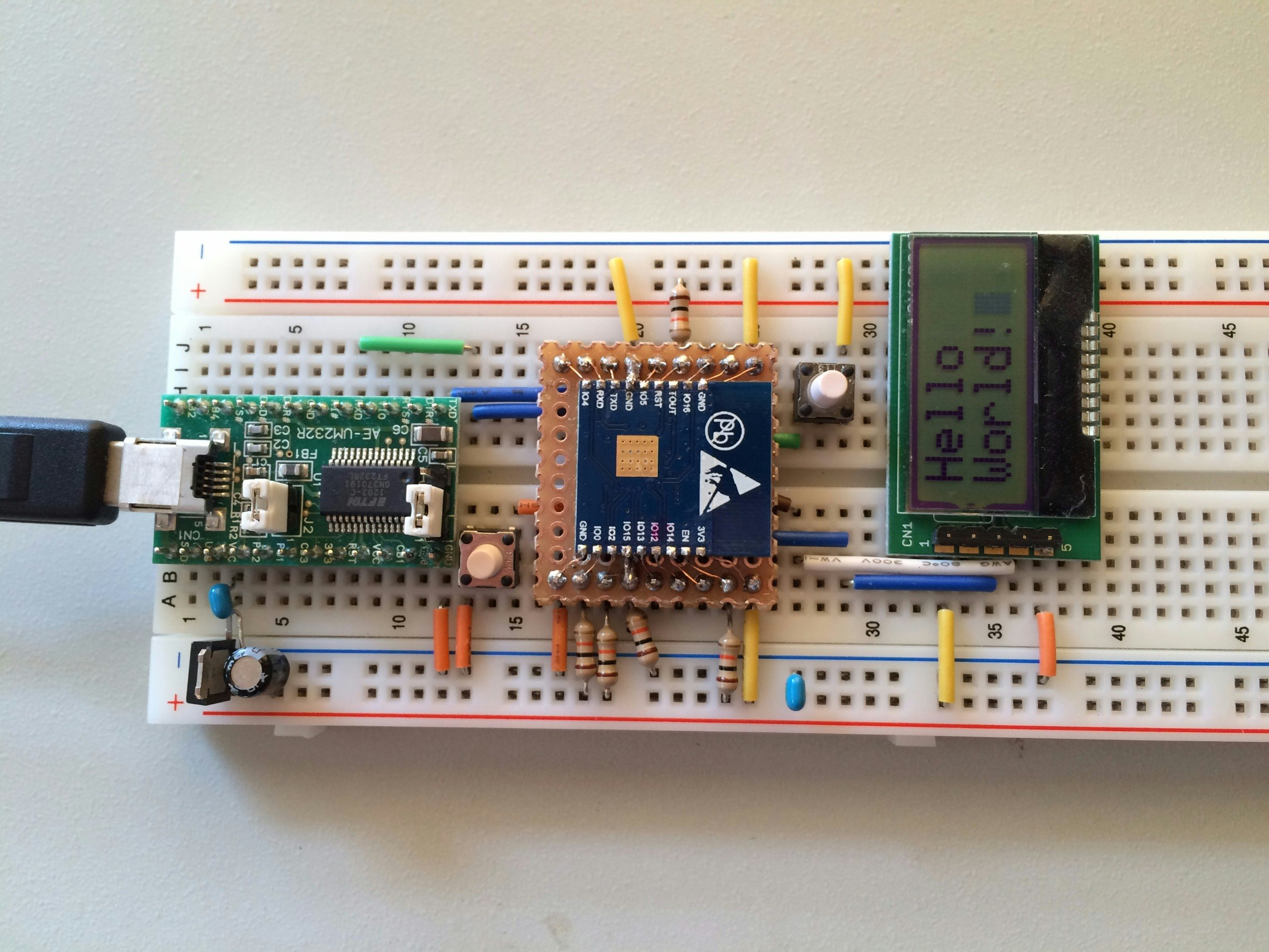
- 書き込みが完了すると通常モードで起動します。
LCD ディスプレイに文字が表示されているはずです。
回路図で ESP-WROOM-02 の EAGLE ライブラリ書いたので公開しておきます。
https://raw.githubusercontent.com/ikesato/eagle-libraries/master/lbr/esp-wroom-02.lbr
よかったらどうぞー。
ESP-WROOM-02 は WiFi モジュールとして使えますが、単体でここまで出来るとは素晴らしい!