This article is for my entry to Pi Zero contest 2016.
https://hackaday.io/project/9526-bring-your-own-pizero-byop
Background
It's good to have a snap cable for GPIO connection between PiZero and other MCUs.
With this snap cable, owners of the PiZeros can be quickly attach to the other MCUs without the need of the soldering of the PiZeros.
Also, breadboard experiment can be started just after unboxing the PiZeros if they the have breadboard.
Bill of materials
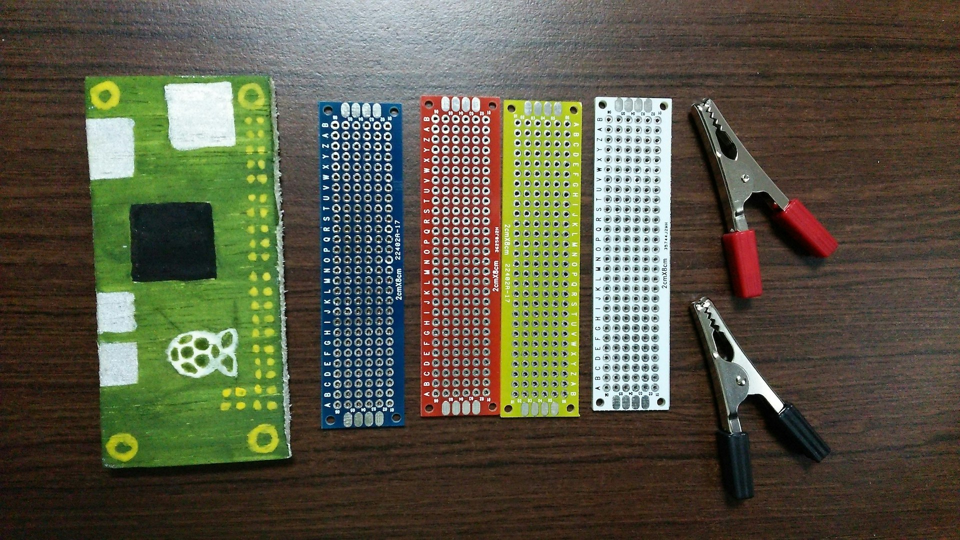
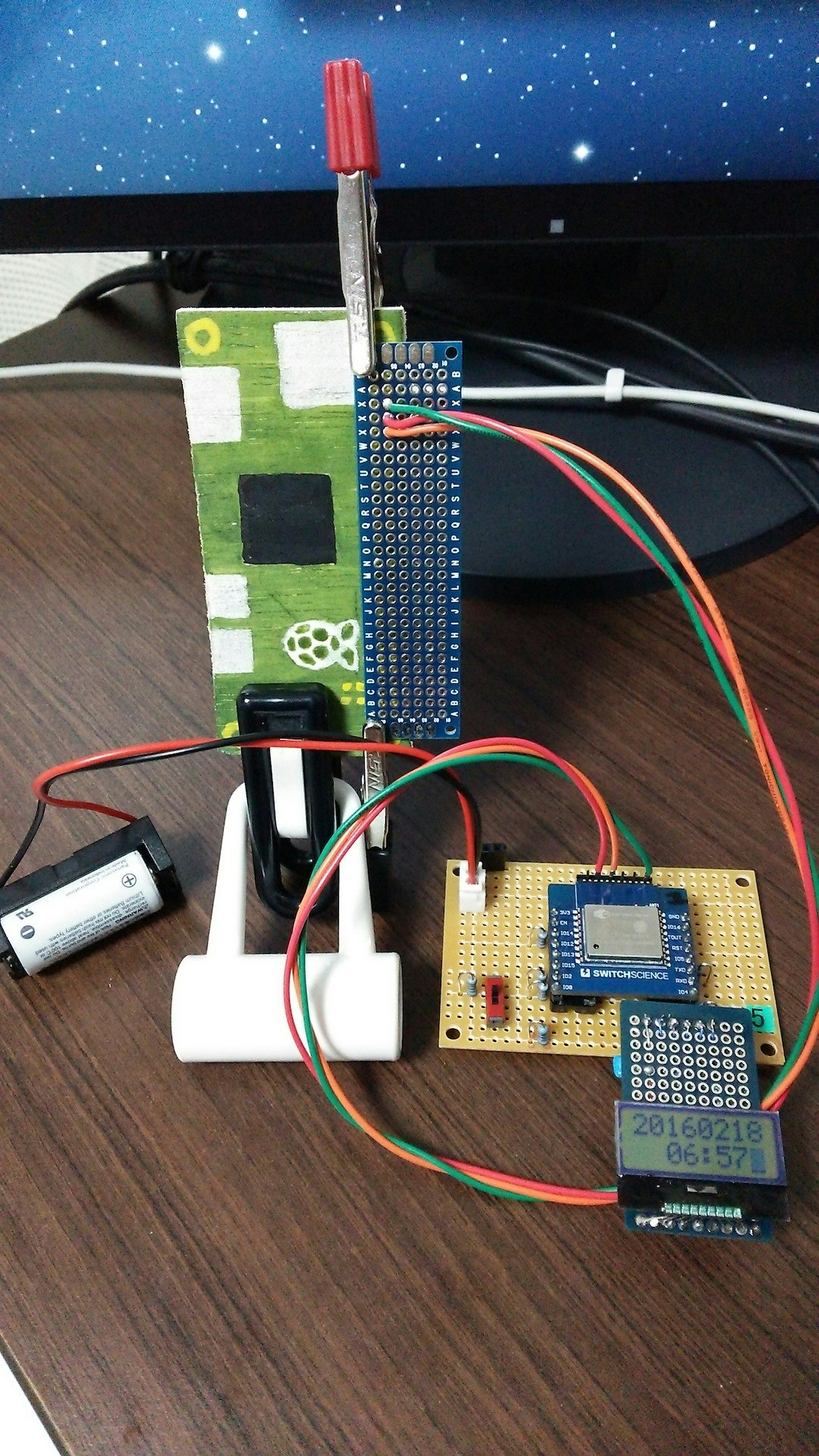
Following is the prototype to show the concept of the GPIO snap cable.
Prepare the followings.
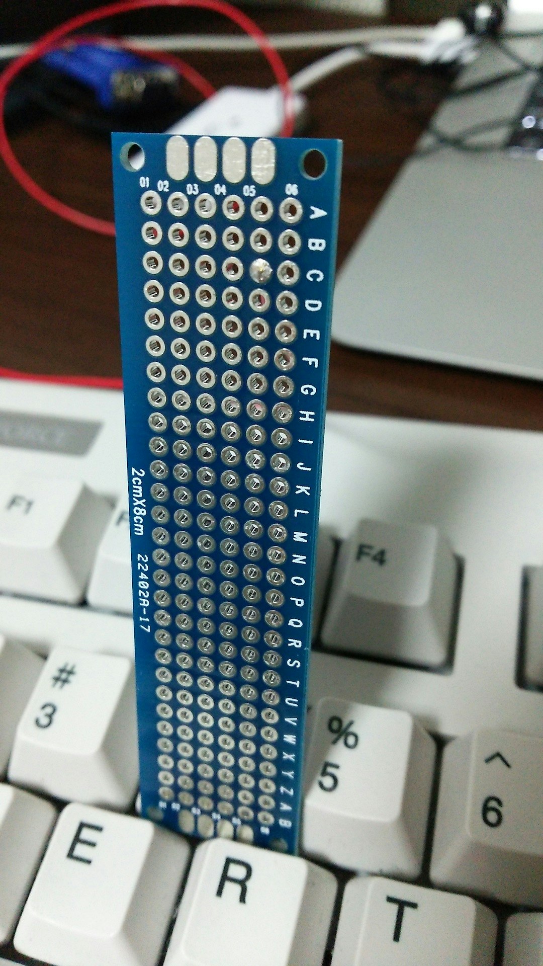
- universal PCB board, which have the size similar to those of PiZero's GPIO pins (2 x 20)
- Alligator Clips, which has the size enough to hold the PiZero and the PCB board together
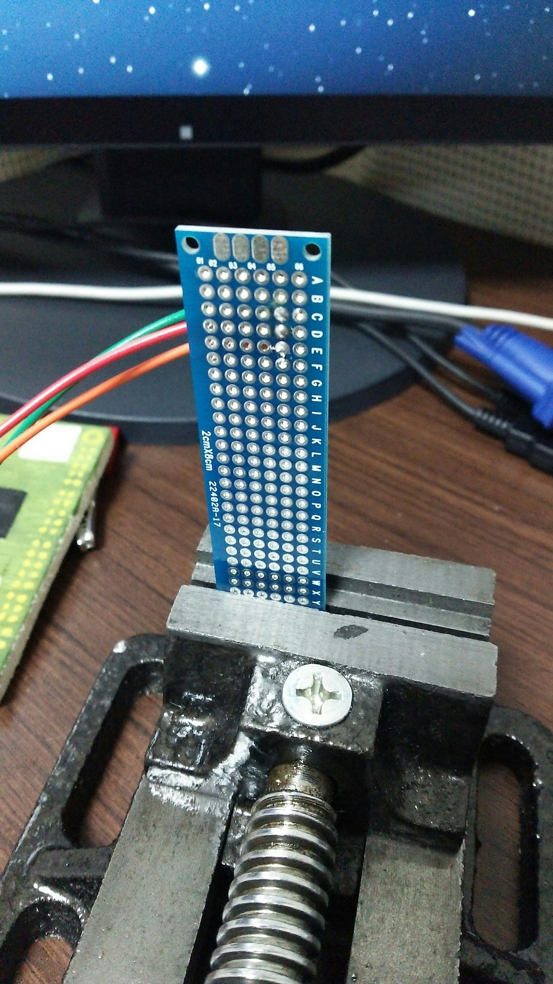
- 24 AWG Wire
- GND (e.g. green) for Pin# 06 of PiZero
- TX (e.g. red) for Pin# 08
- RX (e.g. orange) for Pin# 10
Soldering
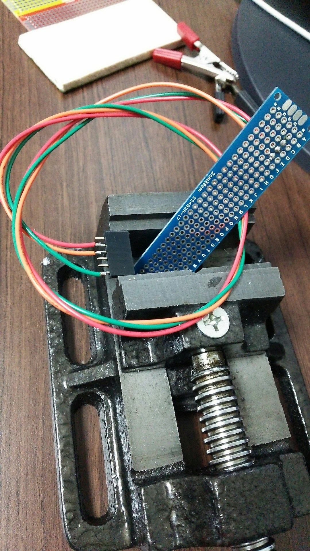
Solder the AWG wires so that on the one side of the PCB Board, the soldered shape can be fit to the GPIOs of the PiZeros.
The possible positions to wire soldering would be the second column of the Board, which will be attached to the Pin# 06, 08, and 10 of the PiZero.
Repeat the procedure for all the three wires.
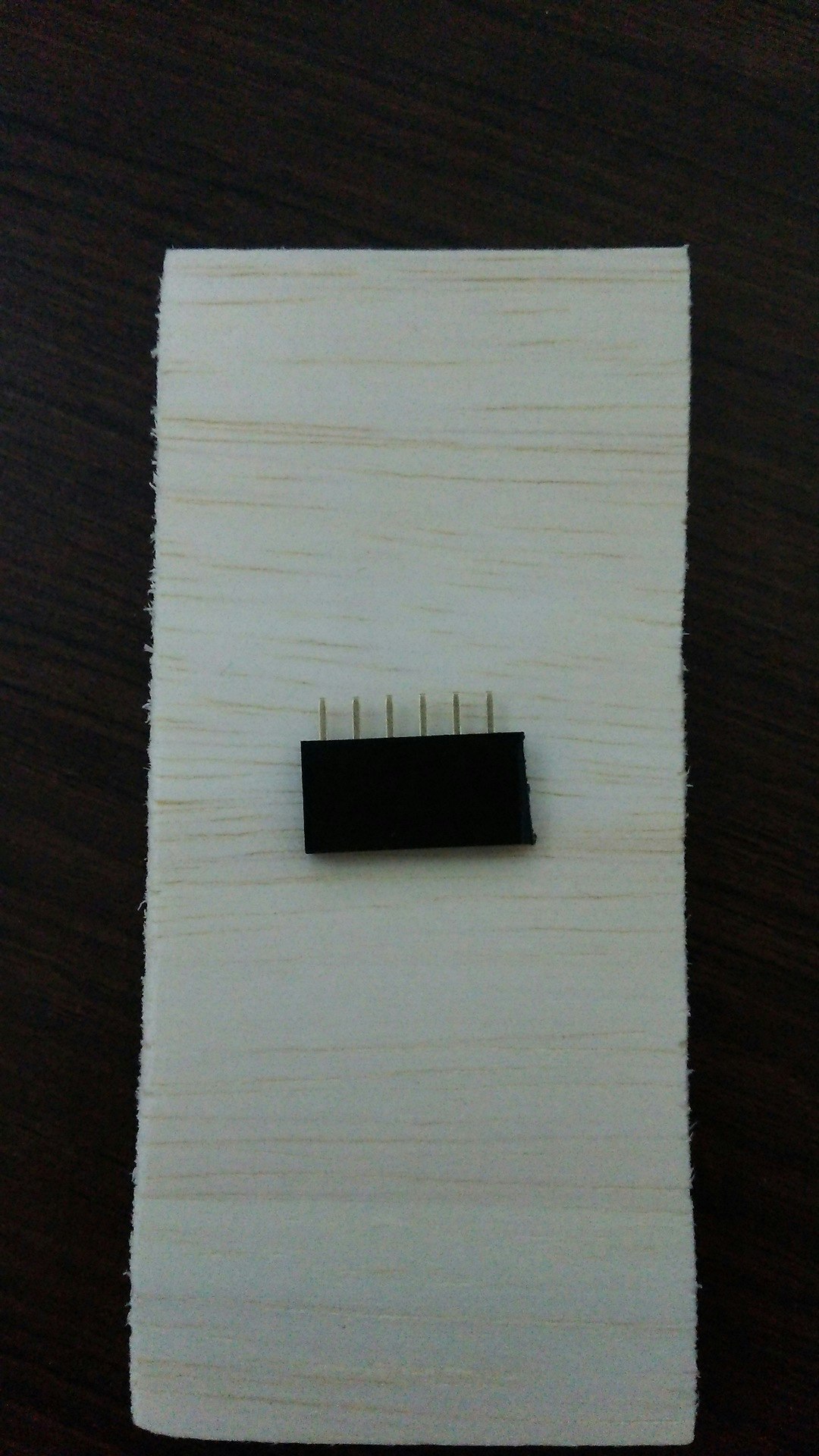
Prepare the I-shaped straight pin header. Cut it to have the 6 pins (or those according to the geometry of your board having the ESP8266).
Solder the other side of the cable to the cut pin header, which has been soldered with the PCB board.
Attachment
Attach the PiZero and the PCB board with the Alligator Clip having care so that any misconnection does not occur on the PiZero. Connect the other side of the cable to the message station (based on the ESP8266 and a 8x2 LCD).
